

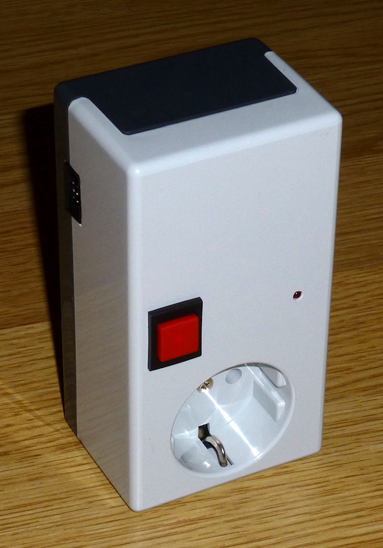
Power Switch
Purpose
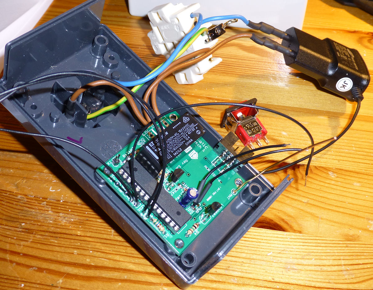
An SHC power switch circuit can be used to switch a low or high voltage. It can be controlled remotely by SHC commands via the base station as well as manually by a switch or a toggle button.
A special feature is its timer function. Using the function, the switch changes its state (e.g. from Off to On) after reception and automatically changes it back after the given amount of time, independent from an existing connection to the base station. This makes sure it switches again even if radio transmission is not possible for whatever reason. As a use case, think about a water pump for plants which automatically switches off after 30 seconds.
Besides a power socket, you could also use the circuit to control other home appliances by connecting their buttons to the relay.
Functions, Behavior
The status can be retrieved with a "Get" or changed with a "Set" or "SetGet". The current state is broadcasted every 30 minutes and some seconds after a change with a "Status". The firmware version is sent about once a day.
Optional Physical Switch
With an additional switch which is connected to an IO pin, the relais state can be calculated as a combination of the state requested by one of the supported messages (e.g. DigitalPin) and the status of the switch. Additionally, the change of the switch state to 'on' or 'off' can be considered with a delay. This means that the resulting relais state is also changed only when the switch stays in that state at least as long as the delay time. The behaviour can be configured in the e2p.
Currently, only one switch is supported on PB7. If you need more, let me know. I'll extend the functionality then.
Use Cases
- Override the normally automatic switching of a relais (by your SHC control logic) with a physical switch temporarily ("forced on" / "forced off").
- Intelligent kitchen hood control that switches it off in case a wood-burning stove is on and the window in the kitchen is not open. This is needed in Germany when the kitchen hood extracts the air to the outside. An environment sensor can be used to detect the temperature and therefore status of the stove. A window sensor connected to the power switch can detect if the window is open.
- Control of the operating time of a robotic lawn mower by interrupting the power supply in the times the mower shall not work. By using a reed contact to detect the mower being in the changing station and using switch mode and switch delay values in the e2p, it is ensured that the mower is charged at least some time after it enters the charging station.
Calculation Logic
In general, the status according digital pin/port command (CMD) and the switch (SW) can be combined by 'and', 'or' or 'xor'. Additionally the switch can be active open or active close and therefore can be inverted ('not'). The resulting settings are as follows:
- CMD (default): Relais is set according received messages, switch is ignored / not connected.
- SW: Relais is set according the connected switch only.
- not SW: Relais is set according the connected switch only (with inverted logic).
- CMD and SW: Relais is on only if requested by command and the switch is on.
- CMD and not SW: Relais is on only if requested by command and the switch is off (inverted logic).
- CMD or SW: Relais is on if requested by command or when switch is on.
- CMD or not SW: Relais is on if requested by command or when switch is off (inverted logic).
- CMD xor SW: Relais is on if request by command and switch state differ.
- CMD xor not SW: Relais is on if request by command and switch state differ (inverted logic).
The other theoretically possible combinations don't make sense, because the relais would never be switched or the status as requested by a message would be inverted only.
Reduced Reception Time
To save power, the power switch can switch off the RFM12 module following a RX (receive) cycle defined in the E2P. This is useful for a battery powered power switch, which can switch on and off something which is also battery powered, is not needed often, and for which it's not important to have the possibility to switch it immediately at any time.
An example use case is to switch the garden irrigation with a valve connected to the same battery, which usually is turned on only some minutes per day. The time for which the RFM12 module is active can be reduced to e.g. 15 seconds per hour. The battery runtime can be drastically extended by that measure.
The RX cycle is defined by the RXCycleOnSec value, which defines how many seconds the device will have the RFM12 module on (actively listening), and the RXCycleOffSec value, which is accordingly the number of seconds the RFM12 module is off per cycle. When the reception is turned off, the device obviously can't react to a message anymore. Therefore, it reports when it goes into active listening mode with a Generic_RXCycle_Deliver message, to be sure the Base Station received it. The home automation system can react on it by controlling the device within the reported RXCycleOnSec time.
Battery Voltage Measurement
Usually the device is powered by a power supply and not with batteries, since the RFM12 is actively listening to receive commands and the device draws too much power. But in some cases (depending on what shall be switched), it could be powered by batteries. With two LiIon 18650 batteries, it runs several weeks. By setting the E2P values accordingly, the battery voltage measurement is activated, and an according BatteryStatus status is sent with the remaining battery capacity percentage.
Supported Messages
- Generic_DeviceInfo_Status
- Generic_HardwareError_Status
- Generic_BatteryStatus_Status
- Generic_RXCycle_Deliver
- GPIO_DigitalPort_Set
- GPIO_DigitalPort_SetGet
- GPIO_DigitalPort_Ack
- GPIO_DigitalPort_AckStatus
- GPIO_DigitalPortTimeout_Set
- GPIO_DigitalPortTimeout_SetGet
- GPIO_DigitalPortTimeout_Ack
- GPIO_DigitalPortTimeout_AckStatus
- GPIO_DigitalPin_Set
- GPIO_DigitalPin_SetGet
- GPIO_DigitalPinTimeout_Set
- GPIO_DigitalPinTimeout_SetGet
E2P Device Configuration
| Offset | Block | Content | Type | Size | Description |
|---|---|---|---|---|---|
| 0 | Hardware Values for hardware setup, which have no special meaning to SHC device concepts + the DeviceType, which decides about the existence of further blocks. | DeviceType | EnumValue | 1 Bytes | The device can check with this value if the EEPROM data is meant for the actual type of device. If not, the device goes into an error mode. Values: 0 = BaseStation, 10 = Proxy, 20 = EnvSensor, 40 = PowerSwitch, 43 = IRTransceiver, 45 = Controller, 50 = RGBDimmer, 60 = Dimmer, 70 = SoilMoistureMeter, 80 = Thermostat, 90 = TeaMaker |
| 8 | OsccalMode | IntValue | 1 Bytes | This value is used to change the speed of the internal oscillator. 0 = don't use OSCCAL calibration (e.g. external crystal oszillator is used). -128 = OSCCAL measure mode: the LED blinks every 60s, so the user can measure the original speed. -127..+127 = The speed is adjusted by the given amount in per mill (e.g. 10 means to speed up the device by +1%). MinVal: -128, MaxVal: 127, Default: 0 | |
| 16 | Reserved | 6 Bytes | n/a | ||
| 64 | Generic This block contains SHC configuration data which every device has. | DeviceID | UIntValue | 12 Bits | The DeviceID identifies the specific unit in the SHC network. It is used to address the device and in messages the device sends. Every device has to have a different DeviceID. MinVal: 0, MaxVal: 4095 |
| 76 | Reserved | 4 Bits | n/a | ||
| 80 | PacketCounter | UIntValue | 3 Bytes | The PacketCounter is counted up throughout the whole lifetime of the device and is used to make the encrypted packets differently from each other every time. MinVal: 0, MaxVal: 16777215 | |
| 104 | Reserved | 19 Bytes | n/a | ||
| 256 | AesKey | ByteArray | 32 Bytes | This key is used to encrypt packets before sending and also used as primary key to decrypt packets. Special devices may have additional keys in their device specific block. | |
| 512 | PowerSwitch This block contains the specific configuration data that only Power Switch devices need. | BaseStationPacketCounter | UIntValue | 3 Bytes | This is the last remembered packet counter of a command from the base station. Packets with the same or lower number are ignored. MinVal: 0, MaxVal: 16777215 |
| 536 | TransceiverWatchdogTimeout | UIntValue | 1 Bytes | Reset RFM12B module if no data is received until timeout is reached. Use this function if your specific transceiver hangs sometimes. Value is in deca seconds. Suggested setting is 48 (for 8 minutes). Set 0 to disable. MinVal: 0, MaxVal: 255, Default: 48 | |
| 544 | StatusCycle | UIntValue | 1 Bytes | This is the number of minutes after which the status should be resent, so in case of a lost message it can be received again. Set 0 to disable. MinVal: 0, MaxVal: 255, Default: 30 | |
| 552 | SupportedSwitches | UIntValue | 1 Bytes | This is the number of connected switches. MinVal: 1, MaxVal: 3 | |
| 560 | CMDState | BoolValue[8] | 1 Bytes x 8 | This field stores the switch state(s) which were requested by one of the supported 'set'/'setget' commands for eight switches to allow restoring the same state after power loss. Fill this with zeros when creating a e2p file! | |
| 624 | CMDTimeout | UIntValue[8] | 2 Bytes x 8 | This field stores the timeout value(s) which were requested by one of the supported 'set'/'setget' commands for eight switches to allow restoring the same state after power loss. Fill this with zeros when creating a e2p file! MinVal: 0, MaxVal: 65767 | |
| 752 | SwitchMode | EnumValue[8] | 1 Bytes x 8 | The mode decides how the optional manual switches are used in combination to the digital pin/port commands to set the relais status. In general, the status according digital pin/port command (CMD) and the switch (SW) can be combined by 'and', 'or' or 'xor'. Additionally the switch can be active open or active close and therefore can be inverted ('not'). 'CMD' and '(not) SW' mean that only the command or switch are considered. The default value is to ignore the optional manual switch. Values: 0 = CMD, 1 = SW, 2 = not SW, 3 = CMD and SW, 4 = CMD and not SW, 5 = CMD or SW, 6 = CMD or not SW, 7 = CMD xor SW, 8 = CMD xor not SW, Default: 0 | |
| 816 | SwitchOnDelay | UIntValue[8] | 2 Bytes x 8 | This field contains for the 8 switches the times in seconds after which the change of a switch to state "ON" is considered to affect the relais state. If the switch changes to "OFF" again within the delay time, it is cleared and no change of the relais state will happen. If the relais state is changed via command within the delay time, the relais state will consider the old switch state until the delay time is over. After restart (power loss), the delay will not be considered, so the switch state is considered immediately. MinVal: 0, MaxVal: 65535, Default: 0 | |
| 944 | SwitchOffDelay | UIntValue[8] | 2 Bytes x 8 | This field contains for the 8 switches the times in seconds after which the change of a switch to state "OFF" is considered to affect the relais state. The behaviour is equivalent to SwitchOnDelay. MinVal: 0, MaxVal: 65535, Default: 0 | |
| 1072 | BatteryType | EnumValue | 1 Bytes | The BatteryType decides if the input voltage is measured and a BatteryStatus message is sent periodically, considering the voltage curve of the selected battery type. Values: 0 = None, 1 = Alkaline_4C_6V, 2 = LiIon_2C_8V, Default: 0 | |
| 1080 | BatteryScaleDivisor | UIntValue | 2 Bytes | This divisor is used to calculate the battery voltage correctly. The divisor is the one (in 1/100) to divide the measurement value of the ADC (between 0 at 0V and 1023 at 3.3V) to get the battery voltage in V. E.g. when a 2C LiIon battery is used and the resistors are chosen as R4 = 22kOhm and R5 = 39kOhm (to not exceed 3.3V at the ADC input pin with max. battery voltage of 8.4V), the divisor is 1023/((39000+22000)/22000*3.3) = 111.8, for better accuracy stored as 11180. MinVal: 0, MaxVal: 65535, Default: 11180 | |
| 1096 | SupportedOutputPins | UIntValue | 1 Bytes | This is the number of output pins which will be used. These are the ones which are referred to in the DigitalPin/DigitalPort messages. The first pin is always used for the relais, which is connected to PC0 (ATMega328 pin 23). The further I/O pins used are: PC1 (pin 24), PC2 (pin 25), PC4 (pin 27), PD4 (pin 6), PB1 (pin 15), PB2 (pin 16), PB6 (pin 9). When SupportedOutputPins is lower or equal 3, the DigitalPort message will contain the status of the physical (input) switches at position 3, 4, 5 and the first two current actual relais/pin states (considering the switch logic) at position 6 and 7. MinVal: 1, MaxVal: 8, Default: 1 | |
| 1104 | HardwareVersion | EnumValue | 1 Bytes | This is the hardware version of the PCB. The info is especially used to configure the RFM12 VCC pin behaviour (which changed in V1.3) and to report the version in the DeviceInfo message. The value 0 (unknown) is defined to allow new firmware to detect that the value was not set in an outdated E2P. Values: 0 = unknown, 1 = V1_2, 2 = V1_3, 3 = V1_4, Default: 3 | |
| 1112 | RXCycleOnSec | UIntValue | 2 Bytes | This is the time in seconds for which the device will stay in receive mode per cycle. 65535 means that the device shall stay in receive mode the whole time (in this case, RXOffSec needs to be set to 0). If RXOnSec and RXOffSec are both 0, the device will also stay in receive mode the whole time. MinVal: 0, MaxVal: 65535, Default: 65535 | |
| 1128 | RXCycleOffSec | UIntValue | 2 Bytes | This is the time in seconds for which the device will turn off reception per cycle. 65535 means that the device shall switch off reception forever (in this case, RXOnSec needs to be set to 0). Consider that the device is never reachable in this case. MinVal: 0, MaxVal: 65535, Default: 0 | |
| 1144 | Reserved | 880 Bytes | n/a | ||
| 8184 | ErrorCode | EnumValue | 1 Bytes | This byte is set by the firmware to distinguish after the restart if a HW watchdog reset or a Transceiver Watchdog reset (SW reset, triggered on purpose by the firmware) occurred. It doesn't matter to which value you set it by e2p coding. Values: 0 = ExternalReset, 1 = BrownOutReset, 2 = WatchdogReset, 3 = TransceiverWatchdogReset, 4 = TransceiverDynamicWatchdogReset, Default: 0 |
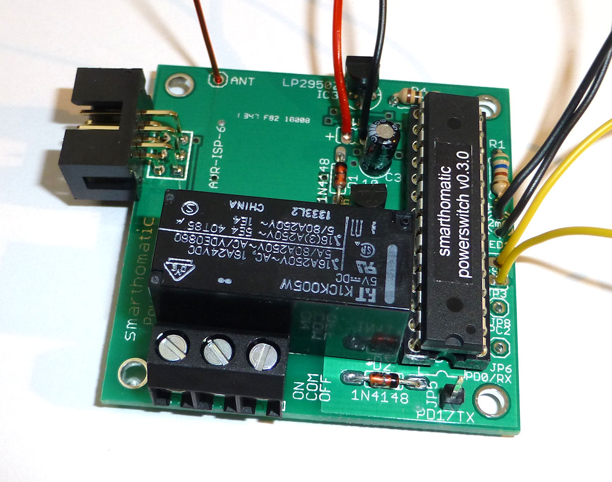
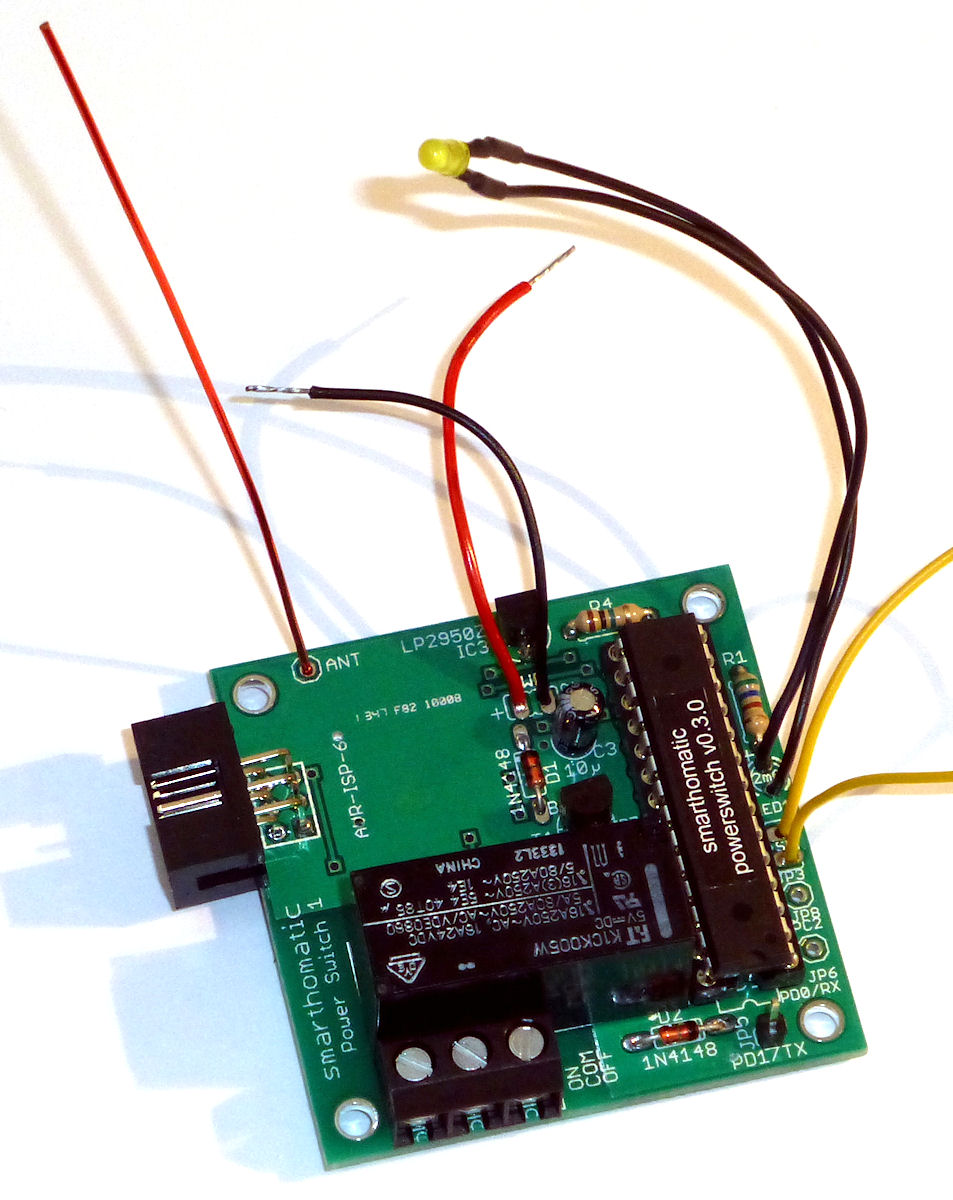
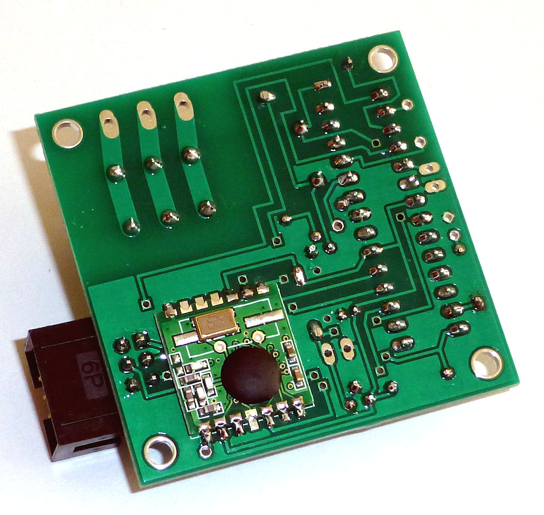
Hardware Overview
| PCB | Power Switch 1 PCB (Conventional THTThrough hole technology This is the conventional technique to stick pins of components through the PCB and solder them. This is easy to build up, unlinke using SMD components., non-SMD) 50 x 50 mm |
|---|---|
| Microcontroller | ATMega 328A-PU (28-pin PDIP) |
| Clock Source | 8 MHz internal R/C oscillator |
| Special Components |
Voltage regulator: voltage regulator 3.3V (TS 2950) or low power step-down PCB (in case device is battery powered) Relay: to connect to the device you want to switch. |
| RFM Transceiver Mode | TX + RX |
| UART | only debug TX |
| Power | 5V power supply, 6V battery or 2C LiIon (5.6-8.4V), with internal 3.3V regulator |
Schematic

Layout

Download
- Firmware Builds for the ATMega
- Hardware Schematics + Layout at Codeberg
- SourceCode at Codeberg
Assembly Instructions
Look into the Wiki for assembly instructions for this device. It would be appreciated if you correct or enhance the description whenever you find potential for improvement.
 | This device uses high voltage. Build and use it at your own risk! Be careful when applying the operating voltage! If you are not familiar with handling high voltages or not allowed to build or use this kind of devices, don't do so. |