

Base Station
Purpose
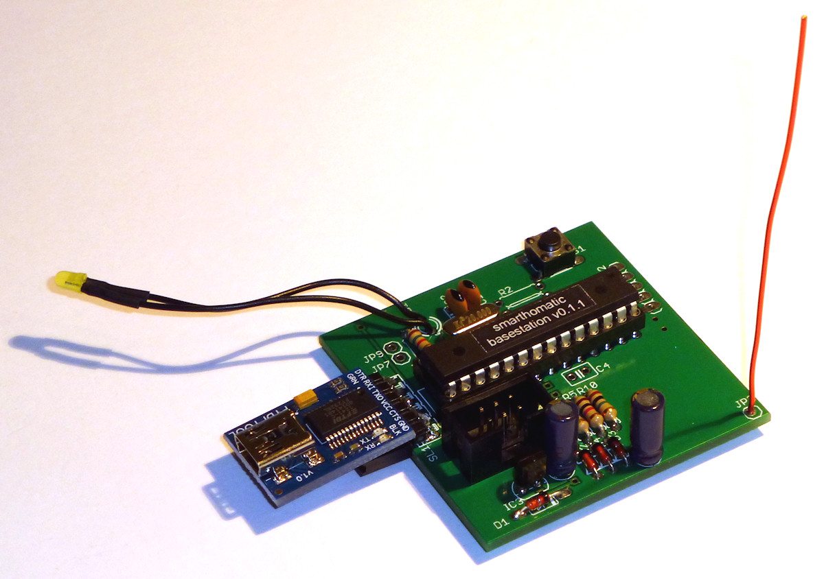
The base station is the master of your SHC network. It communicates to every other device and controls it. It's connected to a PC (or router or NAS etc.) and serves as gateway to your normal home (W)LAN. The data connection is typically implemented through a USB-to-serial converter.
The SHC specific network protocol including encryption and retries is implemented in the base station. But it is no stand-alone device. The higher level logic like feedback loops and control sequences are not defined in the base station, but have to be defined in a server program on the connected PC. This concept is chosen to allow changing control flows easily without the need to reflash the base station. Additionally, there are several good other projects for this purpose and the SHC base station can be integrated into them easily.
In addition to using the received data to control other devices, another common use case is to create statistics.
Communication with the Base Station
When you connect the base station over a serial port to your PC, you can control it with some simple commands. The device may be connected to a physical serial port or over a virtual com port provided by a USB-to-serial converter.
After switching on the base station, you are greeted with the following prompt:
smarthomatic Base Station v0.9.0
(c) 2012..2015 Uwe Freese, www.smarthomatic.org
Device ID: 0
Packet counter: 700
AES key count: 2
UART baud rate: 115200
Waiting for incoming data. Press h for help.
UART Baud Rate
You can choose a baud rate of 19200 (default) and 115200 (fast) by setting an e2p value. Because printing characters on the serial line takes time when sending and receiving packets over the base station, the fast setting reduces these times. There is a typical delay of ~95ms when sending a packet with the default baud rate. Although this should already be considered fast, this time can be reduced to ~18ms with the fast baud rate (times measured from last character entered by the user to the request to the RFM12 to send the packet). When a packet is received, the fast baud rate also speeds up printing the data to the serial line (where it is received by the server application, e.g. FHEM) accordingly.
Receiving Data
If a data packet is received, you can see the raw packet data and the decrypted data.
Received (AES key 0): 5c 8c e1 69 01 70 17 05 d8 14 3d 8f 00 00 00 00
Packet Data: SenderID=23;PacketCounter=94301;MessageType=8;MessageGroupID=10;MessageID=1;MessageData=ec7800000000;Temperature=21.67;Humidity=54.32;Brightness=21;
From v0.10.0 on, it is printed in an abbreviated form:
PKT:SID=31;PC=45642;MT=8;MGID=10;MID=2;MD=724215000000;45b678e6
Detected Weather_HumidityTemperature_Status: Humidity=45.7;Temperature=21.32;
Received (AES key 0): 11 c3 34 92 01 f0 0b 24 a8 14 4e 48 42 a0 00 00
The packet header and header extension is decoded and the according header fields are listed (orange), using the basic packet layout definition. The message data is a series of bytes listed as a hex string (green).
The first line is suffixed with a CRC32 (violet). If the server software (e.g. FHEM) detects a CRC error because of interferences/problems on the serial line, it should ignore the whole packet. The CRC32 is calculated over the string beginning with the 5th character (the S from SID) and ending with the ; before the CRC.
If the MessageGroup and MessageID are known to the base station, the individual values of the message are listed as well (red). But this is not possible with new messages the base station doesn't know. Therefore, only the data string should be used in the end user software and the values should be decoded there, using the packet_layout.xml file. Consider the listing of individual values as a debugging help only.
Sending Requests
You can directly send packets by entering the data as listed in the help:
*** Help ***
h..............this help
rAA............read EEPROM at hex address AA
wAAXX..........write EEPROM at hex address AA to hex value XX
x..............enable writing to EEPROM
z..............disable writing to EEPROM
sKK{T}{X}{D}...Use AES key KK to send a packet with MessageType T, followed
               by all necessary extension header fields and message data.
               Fields are: ReceiverID (RRRR), MessageGroup (GG), MessageID (MM)
               AckSenderID (SSSS), AckPacketCounter (PPPPPP), Error (EE).
               MessageData (DD) can be 0..17 bytes with bits moved to the left.
               End data with ENTER. SenderID, PacketCounter and CRC are automatically added.
sKK00RRRRGGMMDD...........Get
sKK01RRRRGGMMDD...........Set
sKK02RRRRGGMMDD...........SetGet
sKK08GGMMDD...............Status
sKK09SSSSPPPPPPEE.........Ack
sKK0ASSSSPPPPPPEEGGMMDD...AckStatus
As you can see, the AES key number used to encrypt the data packet is entered as first element. It's necessary to use the correct key so the device you want to control can decrypt it. After the message type follow the header extension fields and the message data (if any). These fields depend on the message type you want to send. Again, please look into the basic packet layout and Message Catalog for details.
The CRC32 checksum, SenderID (of the base station) and PacketCounter are added automatically. If you send a request, the packet is added to the request queue automatically before sending.
And here's an example sending a "Set" to a Power Socket:
** Enter AES key nr, MessageType, header extension + data in hex format to send, finish with ENTER. ***
Processing command: s00010028140180
Data byte 0 = 128
Request added to queue.
Request buffer 0: MessageType 1, PacketCounter 0, Timeout 1, Retry 0, Data 02 82 83 00 00
Request Queue 0: ReceiverID 40, Buffer slots 0 - - -

Repeating request.
Packet Data: SenderID=0;PacketCounter=3401;MessageType=1;ReceiverID=40;MessageGroupID=20;MessageID=1;MessageData=8000000000;On=1;TimeoutSec=0;
       AES key: 0
   Unencrypted: e3 b5 0c 8d 00 00 00 d4 91 02 82 83 00 00 00 00
Send encrypted: 25 35 52 e9 29 42 a1 55 3d 4d de bd a7 6f 1b f0
E2P Device Configuration
As you can see below, there are several AES keys stored in the device specific config block. Only these AES keys are used in the BaseStation firmware. The AES key in the Generic block is not used.
| Offset | Block | Content | Type | Size | Description |
|---|---|---|---|---|---|
| 0 | Hardware Values for hardware setup, which have no special meaning to SHC device concepts + the DeviceType, which decides about the existence of further blocks. | DeviceType | EnumValue | 1 Bytes | The device can check with this value if the EEPROM data is meant for the actual type of device. If not, the device goes into an error mode. Values: 0 = BaseStation, 10 = Proxy, 20 = EnvSensor, 40 = PowerSwitch, 43 = IRTransceiver, 45 = Controller, 50 = RGBDimmer, 60 = Dimmer, 70 = SoilMoistureMeter, 80 = Thermostat, 90 = TeaMaker |
| 8 | OsccalMode | IntValue | 1 Bytes | This value is used to change the speed of the internal oscillator. 0 = don't use OSCCAL calibration (e.g. external crystal oszillator is used). -128 = OSCCAL measure mode: the LED blinks every 60s, so the user can measure the original speed. -127..+127 = The speed is adjusted by the given amount in per mill (e.g. 10 means to speed up the device by +1%). MinVal: -128, MaxVal: 127, Default: 0 | |
| 16 | Reserved | 6 Bytes | n/a | ||
| 64 | Generic This block contains SHC configuration data which every device has. | DeviceID | UIntValue | 12 Bits | The DeviceID identifies the specific unit in the SHC network. It is used to address the device and in messages the device sends. Every device has to have a different DeviceID. MinVal: 0, MaxVal: 4095 |
| 76 | Reserved | 4 Bits | n/a | ||
| 80 | PacketCounter | UIntValue | 3 Bytes | The PacketCounter is counted up throughout the whole lifetime of the device and is used to make the encrypted packets differently from each other every time. MinVal: 0, MaxVal: 16777215 | |
| 104 | Reserved | 19 Bytes | n/a | ||
| 256 | AesKey | ByteArray | 32 Bytes | This key is used to encrypt packets before sending and also used as primary key to decrypt packets. Special devices may have additional keys in their device specific block. | |
| 512 | BaseStation This block contains the specific configuration data that only Base Station devices need. | AesKeyCount | UIntValue | 1 Bytes | This is the number of AES keys to use from the AesKeys block. Limit the number to the needed amount to avoid that the base station tries decoding with every one. MinVal: 1, MaxVal: 16, Default: 1 |
| 520 | AesKey | ByteArray[16] | 32 Bytes x 16 | These are all AES keys which can be used to encrypt or decrypt packages at the base station. | |
| 4616 | UartBaudRate | EnumValue | 1 Bytes | Select which baud rate to use for communication with the base station. Use 19200 (0,2% baud rate error @20 MHz) for standard speed, which should work with any connected device. Use 115200 (1,4% baud rate error @20 MHz) to speed up communication to the base station. Values: 19 = 19200, 115 = 115200, Default: 19 | |
| 4624 | TransceiverWatchdogTimeout | UIntValue | 1 Bytes | Reset RFM12B module if no data is received until timeout is reached. Use this function if your specific transceiver hangs sometimes. Value is in deca seconds. Suggested setting is 48 (for 8 minutes). Set 0 to disable. MinVal: 0, MaxVal: 255, Default: 48 | |
| 4632 | Reserved | 444 Bytes | n/a | ||
| 8184 | ErrorCode | EnumValue | 1 Bytes | This byte is set by the firmware to distinguish after the restart if a HW watchdog reset or a Transceiver Watchdog reset (SW reset, triggered on purpose by the firmware) occurred. It doesn't matter to which value you set it by e2p coding. Values: 0 = ExternalReset, 1 = BrownOutReset, 2 = WatchdogReset, 3 = TransceiverWatchdogReset, 4 = TransceiverDynamicWatchdogReset, Default: 0 |
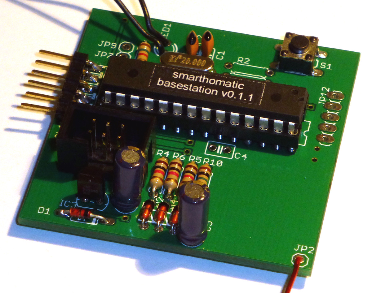
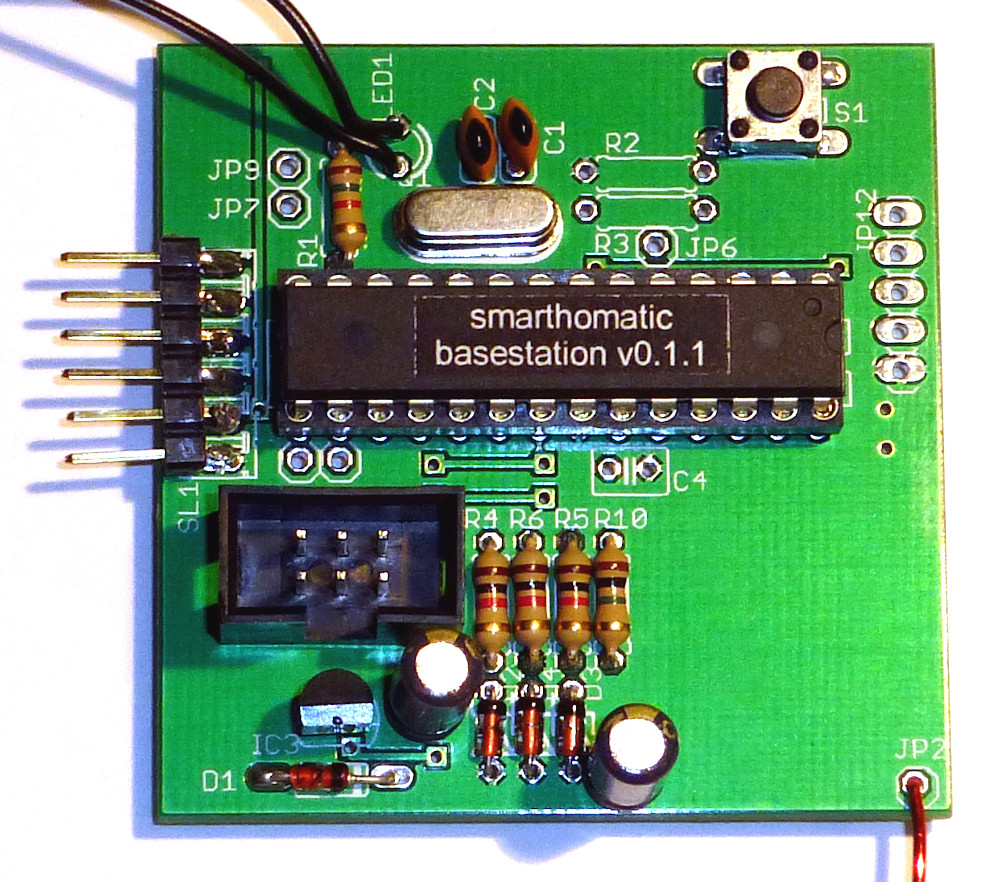
Hardware Overview
| PCB | Conventional THTThrough hole technology This is the conventional technique to stick pins of components through the PCB and solder them. This is easy to build up, unlinke using SMD components. (non-SMD) Generic Maxi Speed PCB 50 x 50 mm |
|---|---|
| Microcontroller | ATMega 328A-PU (28-pin PDIP) |
| Clock Source | 20 MHz external crystal |
| Special Components | USB-to-serial connector |
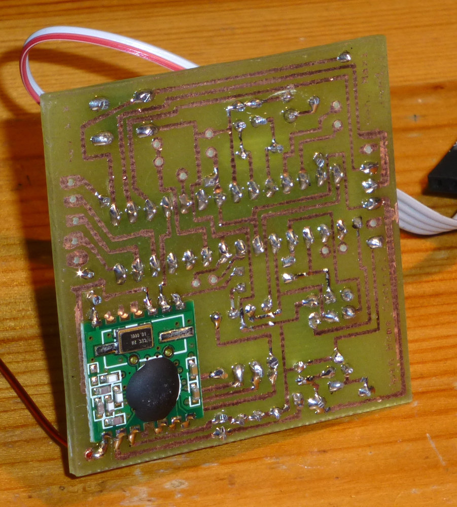
| RFM Transceiver Mode | RX + TX |
| UART | RX + TX, usually connected to a PC with a USB-to-serial converter |
| Power | USB 5V (+ internal 3.3V regulator) |
Schematic

Layout

Download
- Firmware Builds for the ATMega
- Hardware Schematics at Codeberg
- SourceCode at Codeberg
![]()
Assembly Instructions
Look into the Wiki for assembly instructions for this device. It would be appreciated if you correct or enhance the description whenever you find potential for improvement.