

Controller
Purpose
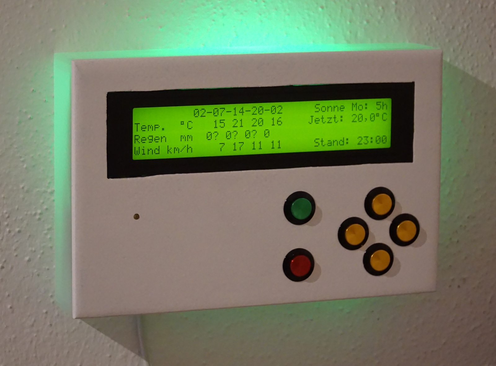
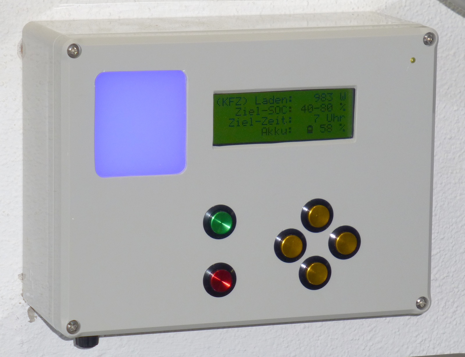
The controller device offers an HMI (human machine interface) with inputs (such as switches and buttons) and outputs (such as a display, speaker, LEDs).
It's purpose is that the user can request actions or set different modes of operation for other smart home devices and to have an overview of the status of smart home devices. It provides a menu with configurable menu items which can be selected by the buttons. With according display messages, the smart home application that's connected to the base station (e.g. FHEM) can send texts to be displayed, set an RGB LED animation or play (warning/status) tones and molodies.
The device supports also virtual pages. That means the texts can be set at line numbers which are higher than the actual amount the LCD provides. With the buttons, the user can switch between the virtual pages and therefore show less important information on request.
As the device usually has a display with background light, and interactions should be fast. It runs at 20 MHz on 5V, with internal voltage regulator to 3,3V for the RFM12 module. Because of the higher power consumption, it is meant to be powered by a 5V power supply.
Inputs and Outputs
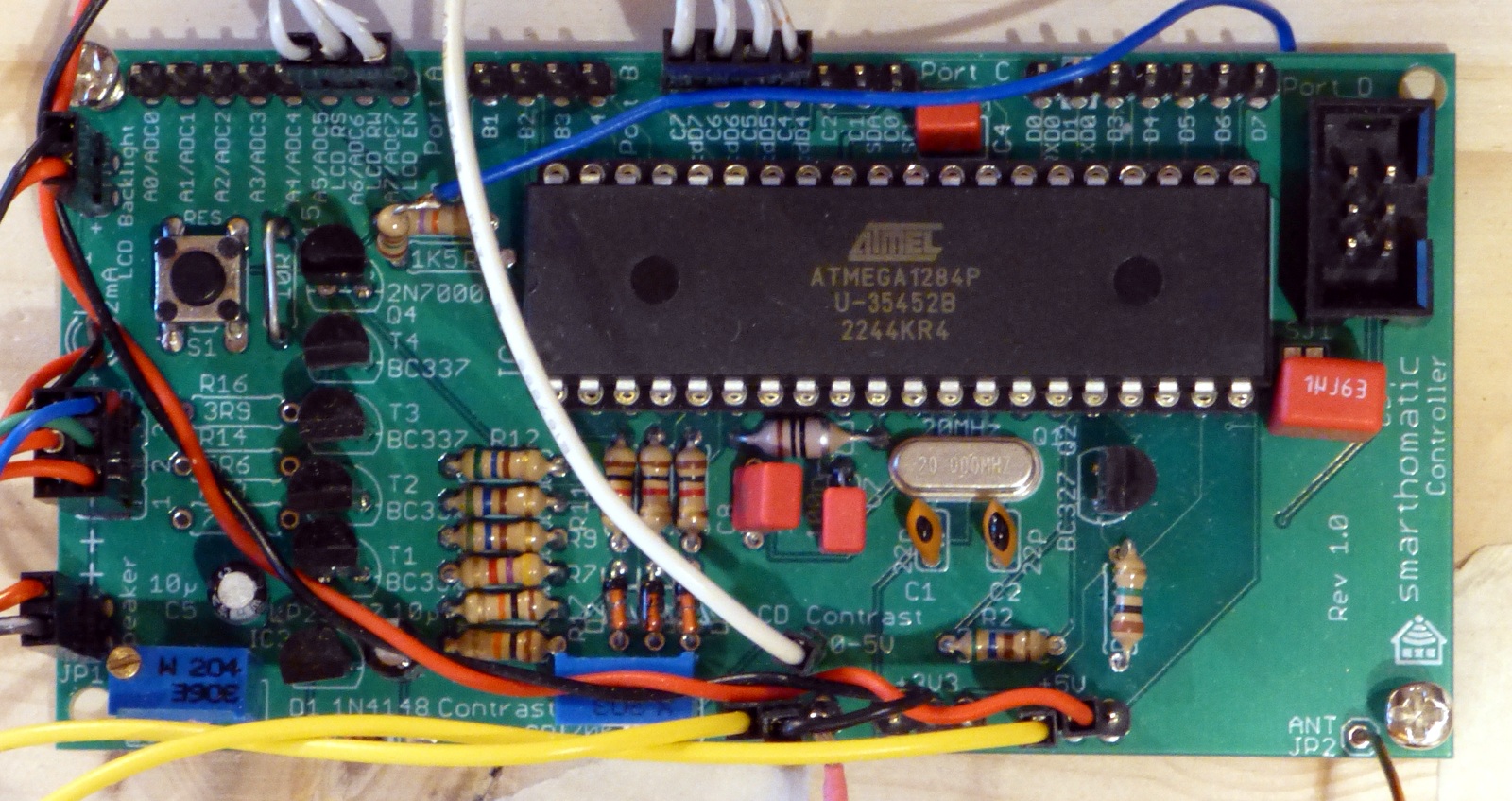
The device uses a bigger ATMega1284 to have more I/O possibilities and to store the text of many menu items. Most I/O pins are available on pin headers on the side of the PCB. The pins which are not used yet could be used in the future for extensions.
Inputs
- Buttons
- Switches
- Analog voltages
Outputs
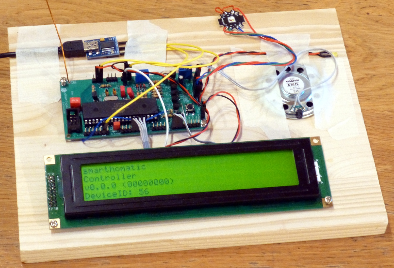
- LCD text display
- Speaker
- RGB LED (as status light like in the RGB Dimmer device, with same functionality for colors and animations)
- I/O pins (to which you can connect e.g. a relais to switch something)
Functions, Behaviour
After building up the device, you have to configure which display, speaker, LEDs you want to use. The menu items you can select can be configured in the e2p. Each menu item consists of a title and a series of menu entries from which the user can select. After the device is configured, you can communicate through the Base Station or the smart home software of your choice that's connected to the base station with the Controller device to test it. You should write down what information should be shown on the display. Afterwards, you have to implement the texts to show in your smart home application.
Supported Messages
- Generic_DeviceInfo_Status
- Generic_HardwareError_Status
- Display_Text_Get/Set/SetGet/Status
- Display_Backlight_Get/Set/SetGet/Status
- Controller_MenuSelection_Get/Set/SetGet/Status/Deliver
- Audio_Tone_Get/Set/SetGet/Status
- Audio_Melody_Get/Set/SetGet/Status
- Dimmer_Brightness_Get/Set/SetGet/Status
- Dimmer_Animation_Get/Set/SetGet/Status
- Dimmer_Color_Get/Set/SetGet/Status
- Dimmer_ColorAnimation_Get/Set/SetGet/Status
E2P Device Configuration
Hardware Overview
| PCB | Controller PCB (SMDSurface-mounted device Using this technique, the components are soldered directly to the surface of the PCB. The components are often very small. Their pin pitch is also small. Building up these devices needs some experience in soldering.) 91 x 50 mm |
|---|---|
| Microcontroller | ATMega 1284P-AU (40-pin DIL) |
| Clock Source | 20 MHz external crystal |
| RFM Transceiver Mode | TX only |
| UART | only debug TX |
| Power | 5V power supply |
Schematic

Layout

Download
- Firmware Builds for the ATMega
- Hardware Schematics + Layout at Codeberg
- SourceCode at Codeberg
Assembly Instructions
Look into the Wiki for assembly instructions for this device. It would be appreciated if you correct or enhance the description whenever you find potential for improvement.