

Proxy
Purpose
The SHC proxy can forward packets between other devices when their distance is too high to have a reliable communication to the base station. The proxy doesn't just duplicate all packets (acting as a repeater), but only forwards packets when one of the rules defined in the e2p matches. It also translates the device IDs and AES keys. This is to avoid sending unnecessary packets, reducing the general risk of collisions because of more traffic and to avoid that a repeated packet and the original one would probably be received both by a receiver.
Functions, Behavior
The proxy listens for all packets and tries to decrypt them with one of the AES keys defined in e2p. When decryption is successful, Sender ID and Receiver ID are compared to the rules. When they match, the packet is modified according rule definition and sent out using the (usually different) AES key from the rule. It's assumed that only a small amount of devices can't be reached from the base station typically, so the number of rules is currently limited to 16 and each rule is only for a specific device ID.
Like all other smarthomatic devices, the proxy can also send a DeviceInfo message to describe the own Device ID and version. But in this case it can send the DeviceInfo for each of the different AES keys, with different cycle times as configured. This is meant to be used to allow other devices using these keys receive valid packets from time to time to reset their TransceiverWatchdogTimeout (only correctly decoded packets count to reset the TransceiverWatchdogTimeout). As the BaseStation and most other devices usually have different keys in use, the devices only accessible through the proxy would otherwise not receive enough valid packets and therefore reset after the timeout is reached.
In the following example, a device with ID 1045 can be reached form the base station using Device ID 45. The proxy takes the packet and translates between base station and the device. The base station can't reach the device 1045 directly, since it doesn't know its AES key and therefore ignores the original packet in case it would be received despite it's usually too far away to receive it.
| Sender ID | Receiver ID | New Sender ID | New Receiver ID | AES Key Number |
|---|---|---|---|---|
| 0 | 45 | 0 | 1045 | 2 |
| 1045 | 0 | 45 | 0 | 0 |
Example rule configuration from e2p
Supported Messages
- Generic_DeviceInfo_Status
- all others as modified copy from received messages
E2P Device Configuration
| Offset | Block | Content | Type | Size | Description |
|---|---|---|---|---|---|
| 0 | Hardware Values for hardware setup, which have no special meaning to SHC device concepts + the DeviceType, which decides about the existence of further blocks. | DeviceType | EnumValue | 1 Bytes | The device can check with this value if the EEPROM data is meant for the actual type of device. If not, the device goes into an error mode. Values: 0 = BaseStation, 10 = Proxy, 20 = EnvSensor, 40 = PowerSwitch, 43 = IRTransceiver, 45 = Controller, 50 = RGBDimmer, 60 = Dimmer, 70 = SoilMoistureMeter, 80 = Thermostat, 90 = TeaMaker |
| 8 | OsccalMode | IntValue | 1 Bytes | This value is used to change the speed of the internal oscillator. 0 = don't use OSCCAL calibration (e.g. external crystal oszillator is used). -128 = OSCCAL measure mode: the LED blinks every 60s, so the user can measure the original speed. -127..+127 = The speed is adjusted by the given amount in per mill (e.g. 10 means to speed up the device by +1%). MinVal: -128, MaxVal: 127, Default: 0 | |
| 16 | Reserved | 6 Bytes | n/a | ||
| 64 | Generic This block contains SHC configuration data which every device has. | DeviceID | UIntValue | 12 Bits | The DeviceID identifies the specific unit in the SHC network. It is used to address the device and in messages the device sends. Every device has to have a different DeviceID. MinVal: 0, MaxVal: 4095 |
| 76 | Reserved | 4 Bits | n/a | ||
| 80 | PacketCounter | UIntValue | 3 Bytes | The PacketCounter is counted up throughout the whole lifetime of the device and is used to make the encrypted packets differently from each other every time. MinVal: 0, MaxVal: 16777215 | |
| 104 | Reserved | 19 Bytes | n/a | ||
| 256 | AesKey | ByteArray | 32 Bytes | This key is used to encrypt packets before sending and also used as primary key to decrypt packets. Special devices may have additional keys in their device specific block. | |
| 512 | Proxy This block contains the specific configuration data that only Proxy devices need. | AesKeyCount | UIntValue | 1 Bytes | This is the number of AES keys to use from the AesKeys block. Limit the number to the needed amount to avoid that the base station tries decoding with every one. MinVal: 1, MaxVal: 16, Default: 1 |
| 520 | AesKey | ByteArray[16] | 32 Bytes x 16 | These are all AES keys which can be used to encrypt or decrypt packages at the base station. | |
| 4616 | VersionStatusCycle | UIntValue[16] | 1 Bytes x 16 | This is the number of deca seconds after which the DeviceInfo is repeated, encoded with each of the AES keys. This should especially be turned on when receiving devices (e.g. PowerSwitch) use the TransceiverWatchdog function and there are no other devices sending regular packets with the same AES key. Since they need to receive a valid packet encoded with their AES key within the configured TransceiverWatchdogTimeout, the proxy can send these. Suggested setting is 29 (for 290s = 4:50 minutes, considering TransceiverWatchdogTimeout values of 15 minutes). The value should be generally 3 times shorter than the TransceiverWatchdogTimeout of the devices needing it. Set 0 to disable. MinVal: 0, MaxVal: 255, Default: 0 | |
| 4744 | TransceiverWatchdogTimeout | UIntValue | 1 Bytes | Reset device if no data is received until timeout is reached. Use this function if your specific transceiver hangs sometimes. Value is in deca seconds. Suggested setting is 48 (for 8 minutes). Set 0 to disable. MinVal: 0, MaxVal: 255, Default: 48 | |
| 4752 | SenderID | UIntValue[16] | 2 Bytes x 16 | These are the Sender Device IDs of the packets that shall be forwarded. Each index corresponds to the values of the following arrays with the same index. The first index with same SenderID and ReceiverID (e.g. 0) is marking from where on the entries are not considered anymore. MinVal: 0, MaxVal: 4095, Default: 0 | |
| 5008 | ReceiverID | UIntValue[16] | 2 Bytes x 16 | These are the Receiver Device IDs of the packets that shall be forwarded. MinVal: 0, MaxVal: 4095, Default: 0 | |
| 5264 | NewSenderID | UIntValue[16] | 2 Bytes x 16 | These are the (modified) Sender IDs that are used in the forwarded packets. MinVal: 0, MaxVal: 4095, Default: 0 | |
| 5520 | NewReceiverID | UIntValue[16] | 2 Bytes x 16 | These are the (modified) Receiver IDs that are used in the forwarded packets. MinVal: 0, MaxVal: 4095, Default: 0 | |
| 5776 | AesKeyNumber | UIntValue[16] | 1 Bytes x 16 | These are the AES key numbers used for the (modified) forwarded packets. MinVal: 0, MaxVal: 15, Default: 0 | |
| 5904 | Reserved | 285 Bytes | n/a | ||
| 8184 | ErrorCode | EnumValue | 1 Bytes | This byte is set by the firmware to distinguish after the restart if a HW watchdog reset or a Transceiver Watchdog reset (SW reset, triggered on purpose by the firmware) occurred. It doesn't matter to which value you set it by e2p coding. Values: 0 = ExternalReset, 1 = BrownOutReset, 2 = WatchdogReset, 3 = TransceiverWatchdogReset, 4 = TransceiverDynamicWatchdogReset, Default: 0 |
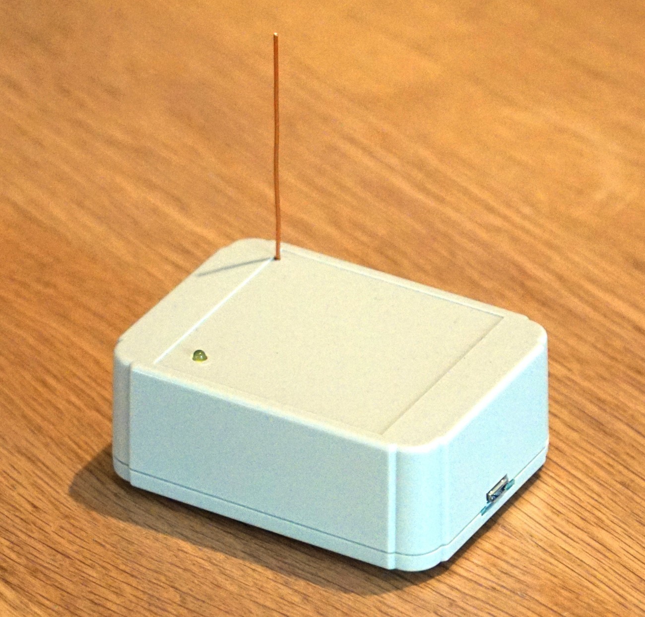
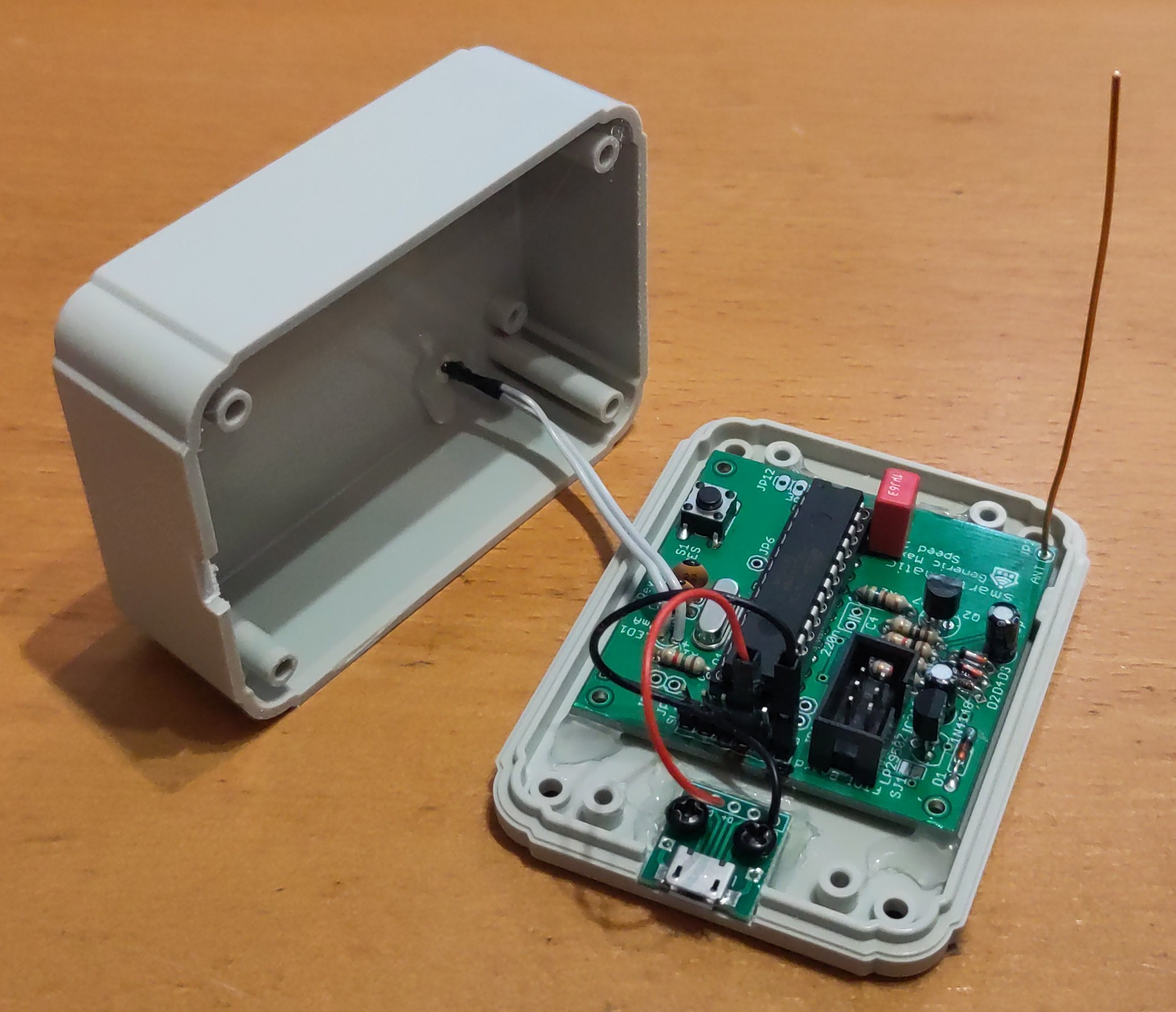
Hardware Overview
The proxy uses the Generic Maxi Speed PCB used as well for the base station.
Download
- Firmware Builds for the ATMega
- Hardware Schematics at Codeberg
- SourceCode at Codeberg
![]()
Assembly Instructions
Look into the Wiki for assembly instructions for the base station, which uses the same hardware.