

Dimmer
Purpose
This dimmer is designed to control CFL (compact fluorescent lamp) or halogen lamp power supplies supporting the OSRAM DIM interface. These power supplies can be dimmed to 1..100% by a 1..10V DC control voltage. Please note that the voltage output is to control such a power supply. You can't connect a lamp directly to this SHC dimmer. The output current is limited to some mA.
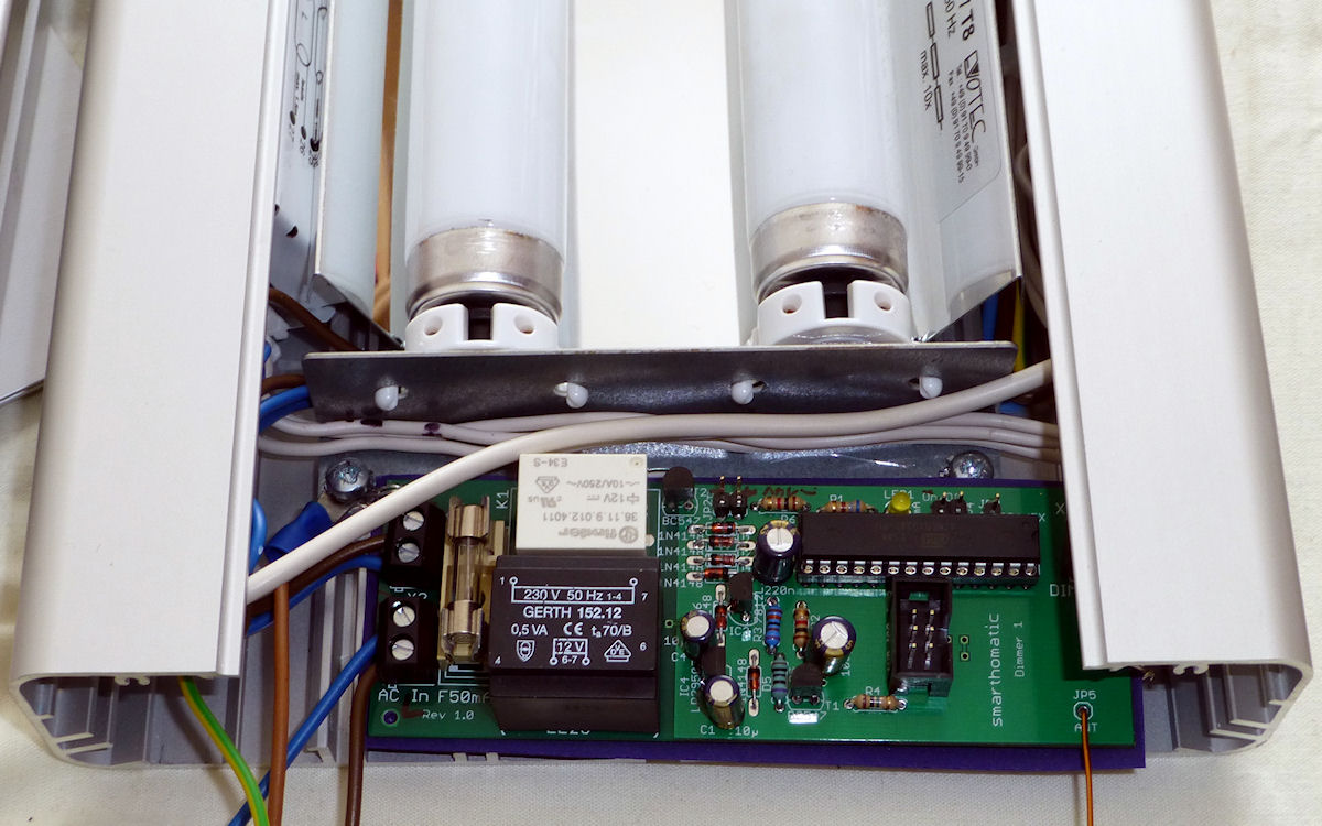
In conjunction with a high frequency electronic power supply (like the OSRAM Quicktronic Deluxe HF Dim T8) and daylight CFL tubes, you get a very nice bright non-flickering light (~50 kHz switching) which you can control remotely. This SHC device is small enough to be directly integrated into a fluorescent lamp housing.
Functions, Behavior
Using this dimmer, you can set the light to a fixed brightness. An optional timeout can be used to switch the light again after a given time. This is useful to ensure the light is switched off after a while without the need of an additional request.
Additionally, you can request the device to start an animation and change the brightness automatically over time. This can be used to simulate a sunset to use this as a wake-up light.
The device sends it status every 30 minutes and its firmware version about once a day.
An internal voltage calibration table is used to adjust the output to exactly 1..10V. There should be no need to change this table though.
Brightness of my CFL lamps
compared to DIM voltage
The brightness calibration table is used to adjust the voltage output to make the controlled power supply / lamp produce a linear brightness curve. For example, my specific CFL tubes in combination with the OSRAM HF Dim T8 already produced a 80% brightness using a medium control voltage of just 5.5V.
Supported Messages
- Generic_DeviceInfo_Status
- Generic_HardwareError_Status
- Dimmer_Brightness_Set/Get/SetGet/Status/Ack/StatusAck
- Dimmer_Animation_Set/Get/SetGet/Status/Ack/StatusAck
E2P Device Configuration
| Offset | Block | Content | Type | Size | Description |
|---|---|---|---|---|---|
| 0 | Hardware Values for hardware setup, which have no special meaning to SHC device concepts + the DeviceType, which decides about the existence of further blocks. | DeviceType | EnumValue | 1 Bytes | The device can check with this value if the EEPROM data is meant for the actual type of device. If not, the device goes into an error mode. Values: 0 = BaseStation, 10 = Proxy, 20 = EnvSensor, 40 = PowerSwitch, 43 = IRTransceiver, 45 = Controller, 50 = RGBDimmer, 60 = Dimmer, 70 = SoilMoistureMeter, 80 = Thermostat, 90 = TeaMaker |
| 8 | OsccalMode | IntValue | 1 Bytes | This value is used to change the speed of the internal oscillator. 0 = don't use OSCCAL calibration (e.g. external crystal oszillator is used). -128 = OSCCAL measure mode: the LED blinks every 60s, so the user can measure the original speed. -127..+127 = The speed is adjusted by the given amount in per mill (e.g. 10 means to speed up the device by +1%). MinVal: -128, MaxVal: 127, Default: 0 | |
| 16 | Reserved | 6 Bytes | n/a | ||
| 64 | Generic This block contains SHC configuration data which every device has. | DeviceID | UIntValue | 12 Bits | The DeviceID identifies the specific unit in the SHC network. It is used to address the device and in messages the device sends. Every device has to have a different DeviceID. MinVal: 0, MaxVal: 4095 |
| 76 | Reserved | 4 Bits | n/a | ||
| 80 | PacketCounter | UIntValue | 3 Bytes | The PacketCounter is counted up throughout the whole lifetime of the device and is used to make the encrypted packets differently from each other every time. MinVal: 0, MaxVal: 16777215 | |
| 104 | Reserved | 19 Bytes | n/a | ||
| 256 | AesKey | ByteArray | 32 Bytes | This key is used to encrypt packets before sending and also used as primary key to decrypt packets. Special devices may have additional keys in their device specific block. | |
| 512 | Dimmer This block contains the specific configuration data that only Dimmer devices need. | BaseStationPacketCounter | UIntValue | 3 Bytes | This is the last remembered packet counter of a command from the base station. Packets with the same or lower number are ignored. MinVal: 0, MaxVal: 16777215 |
| 536 | BrightnessTranslationTable | ByteArray | 101 Bytes | These are the target values (one byte each) for the input brightness of 0, 1, ... 100% to adapt the specific brightness curve of your lamps. Set first byte to FF to not use it. Default: 00 11 15 19 1A 1B 1C 1D 1E 1F 20 21 22 23 24 25 26 27 28 29 2A 2B 2C 2D 2E 2E 2F 30 31 32 33 34 36 37 38 39 3A 3B 3C 3D 3E 40 41 42 43 45 46 47 49 4A 4B 4C 4E 50 51 53 54 56 58 59 5B 5D 5F 61 63 65 67 69 6B 6D 6F 71 73 75 78 7A 7D 80 83 86 89 8B 8F 93 96 9A 9F A3 A7 AB AF B4 BC C2 C9 CF D4 DB E6 F1 FF | |
| 1344 | TransceiverWatchdogTimeout | UIntValue | 1 Bytes | Reset RFM12B module if no data is received until timeout is reached. Use this function if your specific transceiver hangs sometimes. Value is in deca seconds. Suggested setting is 48 (for 8 minutes). Set 0 to disable (default). MinVal: 0, MaxVal: 255, Default: 0 | |
| 1352 | Reserved | 854 Bytes | n/a | ||
| 8184 | ErrorCode | EnumValue | 1 Bytes | This byte is set by the firmware to distinguish after the restart if a HW watchdog reset or a Transceiver Watchdog reset (SW reset, triggered on purpose by the firmware) occurred. It doesn't matter to which value you set it by e2p coding. Values: 0 = ExternalReset, 1 = BrownOutReset, 2 = WatchdogReset, 3 = TransceiverWatchdogReset, 4 = TransceiverDynamicWatchdogReset, Default: 0 |
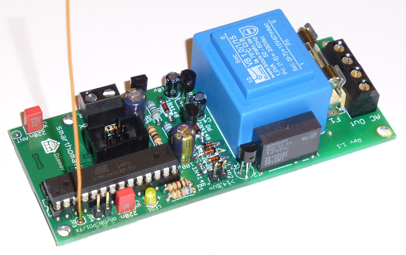
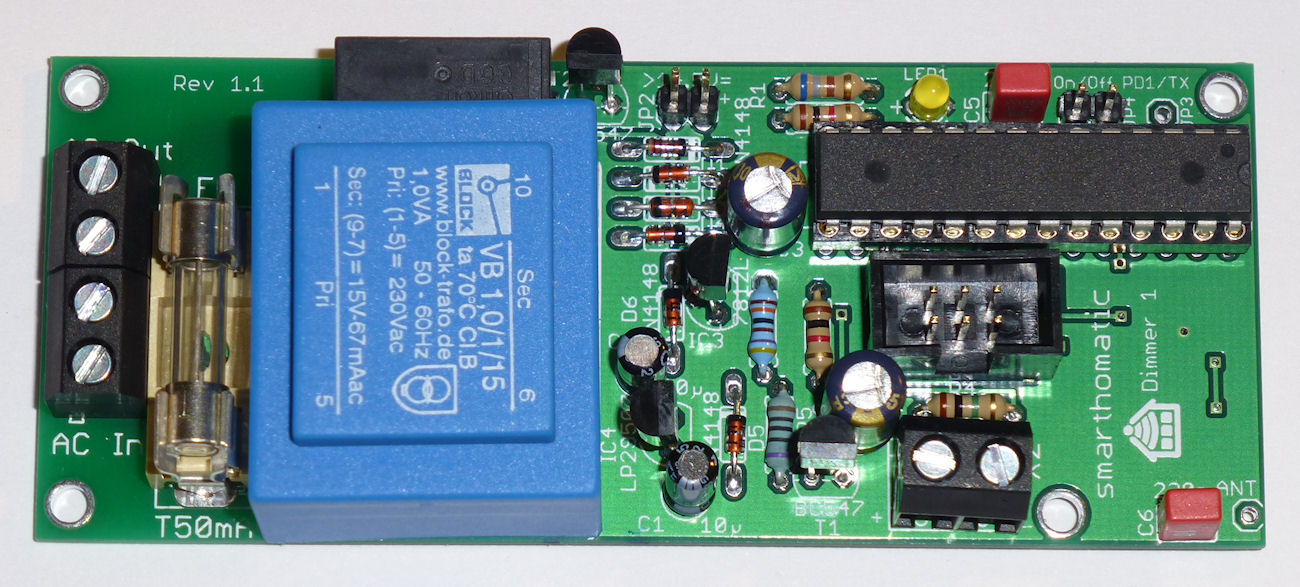
Hardware Overview
| PCB | Conventional THTThrough hole technology This is the conventional technique to stick pins of components through the PCB and solder them. This is easy to build up, unlinke using SMD components. (non-SMD) Specific PCB 41 x 111 mm |
|---|---|
| Microcontroller | ATMega 328A-PU (28-pin PDIP) |
| Clock Source | 8 MHz internal R/C oscillator |
| Special Components | Relais voltage regulators fuse + holder power connectors push-button for manual switching |
| RFM Transceiver Mode | TX + RX |
| UART | only debug TX |
| Power | high voltage 230 V / 115 V AC (depending on the transformer) |
Schematic

Layout

Download
- Firmware Builds for the ATMega
- Hardware Schematics + Layout at Codeberg
- SourceCode at Codeberg
Assembly Instructions
Look into the Wiki for assembly instructions for this device. It would be appreciated if you correct or enhance the description whenever you find potential for improvement.
 | This device uses high voltage. Build and use it at your own risk! Be careful when applying the operating voltage! If you are not familiar with handling high voltages or not allowed to build or use this kind of devices, don't do so. |