

EEPROM Device Configuration
The EEPROM is a memory block in each SHC device which holds configuration information persistently. The configuration can be created and edited with an EEPROM editor and flashed to the device just like the firmware. The firmware reads the EEPROM data and uses it. The layout is defined in a separate file. It is used for different purposes so the layout needs not be hard coded at different places. The layout is automatically used consistently everywhere.
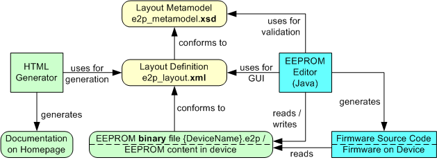
EEPROM Concept Overview
The picture shows how the different files and tools work together. The items are described in detail below.
EEPROM Layout Metamodel
The EEPROM layout cannot have just any arbitrary format. For the different tools to work without problems, an EEPROM layout metamodel (e2p_metamodel.xsd) describes the possible entries. The metamodel should not change over time, whereas the EEPROM layout will change especially when new device types are invented. A change in the metamodel also makes it necessary to change tools, a change in the layout should not.
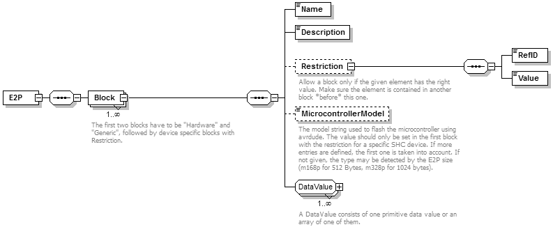
As you can see, the EEPROM layout consists of a series of named blocks, each containing a series of values of different types. The position of the values in the EEPROM (as well as the binary file) result from the number of used bits of all previous elements. This makes it necessary to have a reserved area at some places, but has the advantage that no position information is needed and no values can overlap.
The Restriction subelement of blocks has a special meaning. It defines that a block may only exist when another value matches. This is used to restrict the use of device type specific configuration blocks to the matching DeviceTypeID only. Other future restrictions should be decided with care -- they make it necessary to change the firmware and EEPROM editor (for source code generation) accordingly.
The Microcontroller Model is used as parameter for the flash utility.
Data Types and Byte Layout
The EEPROM values can be from the same data types as defined for the packets. The only difference is that a BoolValue takes one byte (instead of one bit). This is to minimize writing to the same byte in EEPROM especially when arrays of bits are written.
EEPROM Editor
The SHC EEPROM Editor (SHCEE) is a Java program which can be used to create and modify device configurations stored in binary files, which can be flashed to the ATMega's EEPROM. The program uses SwingSwing is the primary toolkit for creating GUIs in Java since version 1.2. It is well known and supported. for its GUI and was designed to run on different PC operating systems easily. It runs at least on Java 1.6 and up.
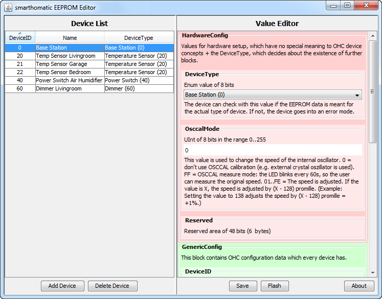
The GUI of the EEPROM editor
All EEPROM files have to be in the program directory and are named {device name}.e2p. The device name part of the filename is used to list the device under this name in the device list on the left side. After selecting a device, the values can be entered or changed in the value editor on the right side. Note that the editor presents you exactly the elements as defined in the layout definition file. The GUI elements are created dynamically. The values are checked against the range and length as defined there. If an EEPROM block has a restriction defined in the layout, it will only appear in the editor panel if the restriction is met. The files can directly be flashed by executing a command line programmer (usually AVRDude).
Firmware Source Code
In addition to edit e2p files, the editor can also generate source code header files for the firmware. An update of these files is only needed when the layout changes or devices are added. This function is not intended for the normal user. The editor is called with a command line argument (/gen) in this case. The generated files contain start positions of the values and enum definitions. See the firmware files on Codeberg for examples.
The Layout
The layout definition is stored in an XML file (e2p_layout.xml). It describes which blocks and values are actually stored in the EEPROM. The layout file has to conform to the metamodel.
Below you find the current layout per DeviceType (with the corresponding DeviceTypeID in brackets) as defined by the XML file. This tables are generated!
BaseStation (0)
| Offset | Block | Content | Type | Size | Description |
|---|---|---|---|---|---|
| 0 | Hardware Values for hardware setup, which have no special meaning to SHC device concepts + the DeviceType, which decides about the existence of further blocks. | DeviceType | EnumValue | 1 Bytes | The device can check with this value if the EEPROM data is meant for the actual type of device. If not, the device goes into an error mode. Values: 0 = BaseStation, 10 = Proxy, 20 = EnvSensor, 40 = PowerSwitch, 43 = IRTransceiver, 45 = Controller, 50 = RGBDimmer, 60 = Dimmer, 70 = SoilMoistureMeter, 80 = Thermostat, 90 = TeaMaker |
| 8 | OsccalMode | IntValue | 1 Bytes | This value is used to change the speed of the internal oscillator. 0 = don't use OSCCAL calibration (e.g. external crystal oszillator is used). -128 = OSCCAL measure mode: the LED blinks every 60s, so the user can measure the original speed. -127..+127 = The speed is adjusted by the given amount in per mill (e.g. 10 means to speed up the device by +1%). MinVal: -128, MaxVal: 127, Default: 0 | |
| 16 | Reserved | 6 Bytes | n/a | ||
| 64 | Generic This block contains SHC configuration data which every device has. | DeviceID | UIntValue | 12 Bits | The DeviceID identifies the specific unit in the SHC network. It is used to address the device and in messages the device sends. Every device has to have a different DeviceID. MinVal: 0, MaxVal: 4095 |
| 76 | Reserved | 4 Bits | n/a | ||
| 80 | PacketCounter | UIntValue | 3 Bytes | The PacketCounter is counted up throughout the whole lifetime of the device and is used to make the encrypted packets differently from each other every time. MinVal: 0, MaxVal: 16777215 | |
| 104 | Reserved | 19 Bytes | n/a | ||
| 256 | AesKey | ByteArray | 32 Bytes | This key is used to encrypt packets before sending and also used as primary key to decrypt packets. Special devices may have additional keys in their device specific block. | |
| 512 | BaseStation This block contains the specific configuration data that only Base Station devices need. | AesKeyCount | UIntValue | 1 Bytes | This is the number of AES keys to use from the AesKeys block. Limit the number to the needed amount to avoid that the base station tries decoding with every one. MinVal: 1, MaxVal: 16, Default: 1 |
| 520 | AesKey | ByteArray[16] | 32 Bytes x 16 | These are all AES keys which can be used to encrypt or decrypt packages at the base station. | |
| 4616 | UartBaudRate | EnumValue | 1 Bytes | Select which baud rate to use for communication with the base station. Use 19200 (0,2% baud rate error @20 MHz) for standard speed, which should work with any connected device. Use 115200 (1,4% baud rate error @20 MHz) to speed up communication to the base station. Values: 19 = 19200, 115 = 115200, Default: 19 | |
| 4624 | TransceiverWatchdogTimeout | UIntValue | 1 Bytes | Reset RFM12B module if no data is received until timeout is reached. Use this function if your specific transceiver hangs sometimes. Value is in deca seconds. Suggested setting is 48 (for 8 minutes). Set 0 to disable. MinVal: 0, MaxVal: 255, Default: 48 | |
| 4632 | Reserved | 444 Bytes | n/a | ||
| 8184 | ErrorCode | EnumValue | 1 Bytes | This byte is set by the firmware to distinguish after the restart if a HW watchdog reset or a Transceiver Watchdog reset (SW reset, triggered on purpose by the firmware) occurred. It doesn't matter to which value you set it by e2p coding. Values: 0 = ExternalReset, 1 = BrownOutReset, 2 = WatchdogReset, 3 = TransceiverWatchdogReset, 4 = TransceiverDynamicWatchdogReset, Default: 0 |
Proxy (10)
| Offset | Block | Content | Type | Size | Description |
|---|---|---|---|---|---|
| 0 | Hardware Values for hardware setup, which have no special meaning to SHC device concepts + the DeviceType, which decides about the existence of further blocks. | DeviceType | EnumValue | 1 Bytes | The device can check with this value if the EEPROM data is meant for the actual type of device. If not, the device goes into an error mode. Values: 0 = BaseStation, 10 = Proxy, 20 = EnvSensor, 40 = PowerSwitch, 43 = IRTransceiver, 45 = Controller, 50 = RGBDimmer, 60 = Dimmer, 70 = SoilMoistureMeter, 80 = Thermostat, 90 = TeaMaker |
| 8 | OsccalMode | IntValue | 1 Bytes | This value is used to change the speed of the internal oscillator. 0 = don't use OSCCAL calibration (e.g. external crystal oszillator is used). -128 = OSCCAL measure mode: the LED blinks every 60s, so the user can measure the original speed. -127..+127 = The speed is adjusted by the given amount in per mill (e.g. 10 means to speed up the device by +1%). MinVal: -128, MaxVal: 127, Default: 0 | |
| 16 | Reserved | 6 Bytes | n/a | ||
| 64 | Generic This block contains SHC configuration data which every device has. | DeviceID | UIntValue | 12 Bits | The DeviceID identifies the specific unit in the SHC network. It is used to address the device and in messages the device sends. Every device has to have a different DeviceID. MinVal: 0, MaxVal: 4095 |
| 76 | Reserved | 4 Bits | n/a | ||
| 80 | PacketCounter | UIntValue | 3 Bytes | The PacketCounter is counted up throughout the whole lifetime of the device and is used to make the encrypted packets differently from each other every time. MinVal: 0, MaxVal: 16777215 | |
| 104 | Reserved | 19 Bytes | n/a | ||
| 256 | AesKey | ByteArray | 32 Bytes | This key is used to encrypt packets before sending and also used as primary key to decrypt packets. Special devices may have additional keys in their device specific block. | |
| 512 | Proxy This block contains the specific configuration data that only Proxy devices need. | AesKeyCount | UIntValue | 1 Bytes | This is the number of AES keys to use from the AesKeys block. Limit the number to the needed amount to avoid that the base station tries decoding with every one. MinVal: 1, MaxVal: 16, Default: 1 |
| 520 | AesKey | ByteArray[16] | 32 Bytes x 16 | These are all AES keys which can be used to encrypt or decrypt packages at the base station. | |
| 4616 | VersionStatusCycle | UIntValue[16] | 1 Bytes x 16 | This is the number of deca seconds after which the DeviceInfo is repeated, encoded with each of the AES keys. This should especially be turned on when receiving devices (e.g. PowerSwitch) use the TransceiverWatchdog function and there are no other devices sending regular packets with the same AES key. Since they need to receive a valid packet encoded with their AES key within the configured TransceiverWatchdogTimeout, the proxy can send these. Suggested setting is 29 (for 290s = 4:50 minutes, considering TransceiverWatchdogTimeout values of 15 minutes). The value should be generally 3 times shorter than the TransceiverWatchdogTimeout of the devices needing it. Set 0 to disable. MinVal: 0, MaxVal: 255, Default: 0 | |
| 4744 | TransceiverWatchdogTimeout | UIntValue | 1 Bytes | Reset device if no data is received until timeout is reached. Use this function if your specific transceiver hangs sometimes. Value is in deca seconds. Suggested setting is 48 (for 8 minutes). Set 0 to disable. MinVal: 0, MaxVal: 255, Default: 48 | |
| 4752 | SenderID | UIntValue[16] | 2 Bytes x 16 | These are the Sender Device IDs of the packets that shall be forwarded. Each index corresponds to the values of the following arrays with the same index. The first index with same SenderID and ReceiverID (e.g. 0) is marking from where on the entries are not considered anymore. MinVal: 0, MaxVal: 4095, Default: 0 | |
| 5008 | ReceiverID | UIntValue[16] | 2 Bytes x 16 | These are the Receiver Device IDs of the packets that shall be forwarded. MinVal: 0, MaxVal: 4095, Default: 0 | |
| 5264 | NewSenderID | UIntValue[16] | 2 Bytes x 16 | These are the (modified) Sender IDs that are used in the forwarded packets. MinVal: 0, MaxVal: 4095, Default: 0 | |
| 5520 | NewReceiverID | UIntValue[16] | 2 Bytes x 16 | These are the (modified) Receiver IDs that are used in the forwarded packets. MinVal: 0, MaxVal: 4095, Default: 0 | |
| 5776 | AesKeyNumber | UIntValue[16] | 1 Bytes x 16 | These are the AES key numbers used for the (modified) forwarded packets. MinVal: 0, MaxVal: 15, Default: 0 | |
| 5904 | Reserved | 285 Bytes | n/a | ||
| 8184 | ErrorCode | EnumValue | 1 Bytes | This byte is set by the firmware to distinguish after the restart if a HW watchdog reset or a Transceiver Watchdog reset (SW reset, triggered on purpose by the firmware) occurred. It doesn't matter to which value you set it by e2p coding. Values: 0 = ExternalReset, 1 = BrownOutReset, 2 = WatchdogReset, 3 = TransceiverWatchdogReset, 4 = TransceiverDynamicWatchdogReset, Default: 0 |
EnvSensor (20)
| Offset | Block | Content | Type | Size | Description |
|---|---|---|---|---|---|
| 0 | Hardware Values for hardware setup, which have no special meaning to SHC device concepts + the DeviceType, which decides about the existence of further blocks. | DeviceType | EnumValue | 1 Bytes | The device can check with this value if the EEPROM data is meant for the actual type of device. If not, the device goes into an error mode. Values: 0 = BaseStation, 10 = Proxy, 20 = EnvSensor, 40 = PowerSwitch, 43 = IRTransceiver, 45 = Controller, 50 = RGBDimmer, 60 = Dimmer, 70 = SoilMoistureMeter, 80 = Thermostat, 90 = TeaMaker |
| 8 | OsccalMode | IntValue | 1 Bytes | This value is used to change the speed of the internal oscillator. 0 = don't use OSCCAL calibration (e.g. external crystal oszillator is used). -128 = OSCCAL measure mode: the LED blinks every 60s, so the user can measure the original speed. -127..+127 = The speed is adjusted by the given amount in per mill (e.g. 10 means to speed up the device by +1%). MinVal: -128, MaxVal: 127, Default: 0 | |
| 16 | Reserved | 6 Bytes | n/a | ||
| 64 | Generic This block contains SHC configuration data which every device has. | DeviceID | UIntValue | 12 Bits | The DeviceID identifies the specific unit in the SHC network. It is used to address the device and in messages the device sends. Every device has to have a different DeviceID. MinVal: 0, MaxVal: 4095 |
| 76 | Reserved | 4 Bits | n/a | ||
| 80 | PacketCounter | UIntValue | 3 Bytes | The PacketCounter is counted up throughout the whole lifetime of the device and is used to make the encrypted packets differently from each other every time. MinVal: 0, MaxVal: 16777215 | |
| 104 | Reserved | 19 Bytes | n/a | ||
| 256 | AesKey | ByteArray | 32 Bytes | This key is used to encrypt packets before sending and also used as primary key to decrypt packets. Special devices may have additional keys in their device specific block. | |
| 512 | EnvSensor This block contains the specific configuration data that only Environment Sensor devices need. | TemperatureSensorType | EnumValue | 1 Bytes | You can choose one of the supported temperature / humidity sensors. Values: 0 = NoSensor, 1 = SHT15, 2 = DS7505, 3 = BMP085, 4 = DS18x20, 5 = SHT2x_HTU21D |
| 520 | HumiditySensorType | EnumValue | 1 Bytes | You can choose one of the supported air humidity sensors. Values: 0 = NoSensor, 1 = SHT15, 2 = SHT2x_HTU21D | |
| 528 | BarometricSensorType | EnumValue | 1 Bytes | You can choose one of the supported barometric pressure sensors. Values: 0 = NoSensor, 1 = BMP085 | |
| 536 | BrightnessSensorType | EnumValue | 1 Bytes | You can choose one of the supported light sensors. Values: 0 = NoSensor, 1 = Photocell | |
| 544 | DistanceSensorType | EnumValue | 1 Bytes | Choose one of the connected distance sensor types. Values: 0 = NoSensor, 1 = SRF02 | |
| 552 | ParticulateMatterSensorType | EnumValue | 1 Bytes | Choose one of the connected particulate matter sensor types. Values: 0 = NoSensor, 1 = SPS30 | |
| 560 | Reserved | 57 Bytes | n/a | ||
| 1016 | PowerPinMode | EnumValue | 1 Bytes | Choose the behaviour of the power pin (PD5) while measuring. It can be turned on before measuring to switch a voltage converter to produce 5V out of the 3V battery power. This is needed for some sensors which need 5V. 5VSensor_Delay1000 means that the pin is switched on when a sensor is configured which needs 5V power (currently SRF02 and SPS30). There's a delay of 1000ms after switching the pin to stabilize the voltage and to ensure the sensor works correctly. Off means the power pin is always off. Values: 0 = Off, 1 = 5VSensor_Delay1000 | |
| 1024 | WakeupInterval | EnumValue | 2 Bytes | Decide after which time the device should be woken up by the RFM12B transceiver to measure or send values. Values: 1018 = 2s, 1274 = 4s, 1467 = 6s, 1530 = 8s, 1692 = 10s, 1770 = 15s, 1948 = 20s, 2027 = 30s, 2224 = 45s, 2421 = 60s, 2450 = 75s, 2480 = 90s, 2509 = 105s, 2538 = 2m, 2736 = 3m, 2794 = 4m, 2962 = 5m, 3050 = 8m, 3248 = 12m, 3292 = 15m, 3474 = 20m, 3548 = 30m, 3804 = 1h, 4060 = 2h, 4261 = 3h, 4316 = 4h, 4517 = 6h, 4572 = 8h, 4773 = 12h, 4828 = 16h, Default: 2509 | |
| 1040 | TemperatureMeasuringInterval | UIntValue | 1 Bytes | The number of times the device wakes up before this value is measured. MinVal: 1, MaxVal: 255, Default: 1 | |
| 1048 | TemperatureAveragingInterval | UIntValue | 1 Bytes | The number of values whose average is calculated before sending. MinVal: 1, MaxVal: 16, Default: 4 | |
| 1056 | HumidityMeasuringInterval | UIntValue | 1 Bytes | The number of times the device wakes up before this value is measured. MinVal: 1, MaxVal: 255, Default: 1 | |
| 1064 | HumidityAveragingInterval | UIntValue | 1 Bytes | The number of values whose average is calculated before sending. MinVal: 1, MaxVal: 16, Default: 4 | |
| 1072 | BarometricMeasuringInterval | UIntValue | 1 Bytes | The number of times the device wakes up before this value is measured. MinVal: 1, MaxVal: 255, Default: 1 | |
| 1080 | BarometricAveragingInterval | UIntValue | 1 Bytes | The number of values whose average is calculated before sending. MinVal: 1, MaxVal: 16, Default: 4 | |
| 1088 | BrightnessMeasuringInterval | UIntValue | 1 Bytes | The number of times the device wakes up before this value is measured. MinVal: 1, MaxVal: 255, Default: 1 | |
| 1096 | BrightnessAveragingInterval | UIntValue | 1 Bytes | The number of values whose average is calculated before sending. MinVal: 1, MaxVal: 16, Default: 4 | |
| 1104 | DistanceMeasuringInterval | UIntValue | 1 Bytes | The number of times the device wakes up before this value is measured. MinVal: 1, MaxVal: 255, Default: 4 | |
| 1112 | DistanceAveragingInterval | UIntValue | 1 Bytes | The number of values whose average is calculated before sending. MinVal: 1, MaxVal: 16, Default: 1 | |
| 1120 | DigitalInputMeasuringInterval | UIntValue | 1 Bytes | The number of times the device wakes up before this value is measured. MinVal: 1, MaxVal: 255, Default: 1 | |
| 1128 | DigitalInputAveragingInterval | UIntValue | 1 Bytes | The number of values whose average is calculated before sending. MinVal: 1, MaxVal: 16, Default: 6 | |
| 1136 | AnalogInputMeasuringInterval | UIntValue | 1 Bytes | The number of times the device wakes up before this value is measured. MinVal: 1, MaxVal: 255, Default: 1 | |
| 1144 | AnalogInputAveragingInterval | UIntValue | 1 Bytes | The number of values whose average is calculated before sending. MinVal: 1, MaxVal: 16, Default: 6 | |
| 1152 | ParticulateMatterMeasuringInterval | UIntValue | 1 Bytes | The number of times the device wakes up before this value is measured. MinVal: 1, MaxVal: 255, Default: 1 | |
| 1160 | ParticulateMatterAveragingInterval | UIntValue | 1 Bytes | The number of values whose average is calculated before sending. MinVal: 1, MaxVal: 16, Default: 4 | |
| 1168 | Reserved | 46 Bytes | n/a | ||
| 1536 | DigitalInputPin | EnumValue[8] | 1 Bytes x 8 | You can choose up to 8 GPIO pins as digital input. The enum values are counting through every pin from port B, C and D, leaving out the pins that are not accessible because otherwise used. Values: 0 = Unused, 2 = PB1, 3 = PB2, 7 = PB6, 8 = PB7, 10 = PC1, 11 = PC2, 12 = PC3, 13 = PC4, 14 = PC5, 20 = PD3, 21 = PD4, 22 = PD5, 23 = PD6 | |
| 1600 | DigitalInputPullUpResistor | BoolValue[8] | 1 Bytes x 8 | Decide if you want to switch on the pull-up resistor at each input pin you have chosen. (If you connect a simple switch connected to ground, you typically want this.) | |
| 1664 | DigitalInputTriggerMode | EnumValue[8] | 1 Bytes x 8 | The mode decides how the device detects changes and when a new message is sent. Off means the value is sent after a full cycle time only. In any other case, the device wakes up immediately after a change. A status is then sent either when the level is going up, down or on change. Values: 0 = Off, 1 = Up, 2 = Down, 3 = Change | |
| 1728 | Reserved | 40 Bytes | n/a | ||
| 2048 | AnalogInputPin | EnumValue[5] | 1 Bytes x 5 | You can choose up to 5 ADC pins as analog input. The enum values are a reduced set of the ones from the digital input. Values: 0 = Unused, 10 = PC1, 11 = PC2, 12 = PC3, 13 = PC4, 14 = PC5 | |
| 2088 | AnalogInputTriggerMode | EnumValue[5] | 1 Bytes x 5 | The mode decides how the device detects changes and when a new message is sent. The voltage level is measured in the configured interval. When the mode is set to off, the status is only sent after a full averaging cycle. In the other modes, a status is sent when the level is going up, down or changes according to the trigger level. Values: 0 = Off, 1 = Up, 2 = Down, 3 = Change | |
| 2128 | AnalogInputTriggerThreshold | UIntValue[5] | 2 Bytes x 5 | The threshold in millivolts is used when the trigger mode is on. MinVal: 0, MaxVal: 1100 | |
| 2208 | AnalogInputTriggerHysteresis | UIntValue[5] | 2 Bytes x 5 | The hysteresis in millivolts is used when the trigger mode is on. It can avoid the trigger firing too often if you measure a slighty changing voltage. Because of noise and accuracy limits of the ADC, you should set a positive hysteresis in any case. MinVal: 0, MaxVal: 1100 | |
| 2288 | Reserved | 34 Bytes | n/a | ||
| 2560 | Reserved | 704 Bytes | n/a |
PowerSwitch (40)
| Offset | Block | Content | Type | Size | Description |
|---|---|---|---|---|---|
| 0 | Hardware Values for hardware setup, which have no special meaning to SHC device concepts + the DeviceType, which decides about the existence of further blocks. | DeviceType | EnumValue | 1 Bytes | The device can check with this value if the EEPROM data is meant for the actual type of device. If not, the device goes into an error mode. Values: 0 = BaseStation, 10 = Proxy, 20 = EnvSensor, 40 = PowerSwitch, 43 = IRTransceiver, 45 = Controller, 50 = RGBDimmer, 60 = Dimmer, 70 = SoilMoistureMeter, 80 = Thermostat, 90 = TeaMaker |
| 8 | OsccalMode | IntValue | 1 Bytes | This value is used to change the speed of the internal oscillator. 0 = don't use OSCCAL calibration (e.g. external crystal oszillator is used). -128 = OSCCAL measure mode: the LED blinks every 60s, so the user can measure the original speed. -127..+127 = The speed is adjusted by the given amount in per mill (e.g. 10 means to speed up the device by +1%). MinVal: -128, MaxVal: 127, Default: 0 | |
| 16 | Reserved | 6 Bytes | n/a | ||
| 64 | Generic This block contains SHC configuration data which every device has. | DeviceID | UIntValue | 12 Bits | The DeviceID identifies the specific unit in the SHC network. It is used to address the device and in messages the device sends. Every device has to have a different DeviceID. MinVal: 0, MaxVal: 4095 |
| 76 | Reserved | 4 Bits | n/a | ||
| 80 | PacketCounter | UIntValue | 3 Bytes | The PacketCounter is counted up throughout the whole lifetime of the device and is used to make the encrypted packets differently from each other every time. MinVal: 0, MaxVal: 16777215 | |
| 104 | Reserved | 19 Bytes | n/a | ||
| 256 | AesKey | ByteArray | 32 Bytes | This key is used to encrypt packets before sending and also used as primary key to decrypt packets. Special devices may have additional keys in their device specific block. | |
| 512 | PowerSwitch This block contains the specific configuration data that only Power Switch devices need. | BaseStationPacketCounter | UIntValue | 3 Bytes | This is the last remembered packet counter of a command from the base station. Packets with the same or lower number are ignored. MinVal: 0, MaxVal: 16777215 |
| 536 | TransceiverWatchdogTimeout | UIntValue | 1 Bytes | Reset RFM12B module if no data is received until timeout is reached. Use this function if your specific transceiver hangs sometimes. Value is in deca seconds. Suggested setting is 48 (for 8 minutes). Set 0 to disable. MinVal: 0, MaxVal: 255, Default: 48 | |
| 544 | StatusCycle | UIntValue | 1 Bytes | This is the number of minutes after which the status should be resent, so in case of a lost message it can be received again. Set 0 to disable. MinVal: 0, MaxVal: 255, Default: 30 | |
| 552 | SupportedSwitches | UIntValue | 1 Bytes | This is the number of connected switches. MinVal: 1, MaxVal: 3 | |
| 560 | CMDState | BoolValue[8] | 1 Bytes x 8 | This field stores the switch state(s) which were requested by one of the supported 'set'/'setget' commands for eight switches to allow restoring the same state after power loss. Fill this with zeros when creating a e2p file! | |
| 624 | CMDTimeout | UIntValue[8] | 2 Bytes x 8 | This field stores the timeout value(s) which were requested by one of the supported 'set'/'setget' commands for eight switches to allow restoring the same state after power loss. Fill this with zeros when creating a e2p file! MinVal: 0, MaxVal: 65767 | |
| 752 | SwitchMode | EnumValue[8] | 1 Bytes x 8 | The mode decides how the optional manual switches are used in combination to the digital pin/port commands to set the relais status. In general, the status according digital pin/port command (CMD) and the switch (SW) can be combined by 'and', 'or' or 'xor'. Additionally the switch can be active open or active close and therefore can be inverted ('not'). 'CMD' and '(not) SW' mean that only the command or switch are considered. The default value is to ignore the optional manual switch. Values: 0 = CMD, 1 = SW, 2 = not SW, 3 = CMD and SW, 4 = CMD and not SW, 5 = CMD or SW, 6 = CMD or not SW, 7 = CMD xor SW, 8 = CMD xor not SW, Default: 0 | |
| 816 | SwitchOnDelay | UIntValue[8] | 2 Bytes x 8 | This field contains for the 8 switches the times in seconds after which the change of a switch to state "ON" is considered to affect the relais state. If the switch changes to "OFF" again within the delay time, it is cleared and no change of the relais state will happen. If the relais state is changed via command within the delay time, the relais state will consider the old switch state until the delay time is over. After restart (power loss), the delay will not be considered, so the switch state is considered immediately. MinVal: 0, MaxVal: 65535, Default: 0 | |
| 944 | SwitchOffDelay | UIntValue[8] | 2 Bytes x 8 | This field contains for the 8 switches the times in seconds after which the change of a switch to state "OFF" is considered to affect the relais state. The behaviour is equivalent to SwitchOnDelay. MinVal: 0, MaxVal: 65535, Default: 0 | |
| 1072 | BatteryType | EnumValue | 1 Bytes | The BatteryType decides if the input voltage is measured and a BatteryStatus message is sent periodically, considering the voltage curve of the selected battery type. Values: 0 = None, 1 = Alkaline_4C_6V, 2 = LiIon_2C_8V, Default: 0 | |
| 1080 | BatteryScaleDivisor | UIntValue | 2 Bytes | This divisor is used to calculate the battery voltage correctly. The divisor is the one (in 1/100) to divide the measurement value of the ADC (between 0 at 0V and 1023 at 3.3V) to get the battery voltage in V. E.g. when a 2C LiIon battery is used and the resistors are chosen as R4 = 22kOhm and R5 = 39kOhm (to not exceed 3.3V at the ADC input pin with max. battery voltage of 8.4V), the divisor is 1023/((39000+22000)/22000*3.3) = 111.8, for better accuracy stored as 11180. MinVal: 0, MaxVal: 65535, Default: 11180 | |
| 1096 | SupportedOutputPins | UIntValue | 1 Bytes | This is the number of output pins which will be used. These are the ones which are referred to in the DigitalPin/DigitalPort messages. The first pin is always used for the relais, which is connected to PC0 (ATMega328 pin 23). The further I/O pins used are: PC1 (pin 24), PC2 (pin 25), PC4 (pin 27), PD4 (pin 6), PB1 (pin 15), PB2 (pin 16), PB6 (pin 9). When SupportedOutputPins is lower or equal 3, the DigitalPort message will contain the status of the physical (input) switches at position 3, 4, 5 and the first two current actual relais/pin states (considering the switch logic) at position 6 and 7. MinVal: 1, MaxVal: 8, Default: 1 | |
| 1104 | HardwareVersion | EnumValue | 1 Bytes | This is the hardware version of the PCB. The info is especially used to configure the RFM12 VCC pin behaviour (which changed in V1.3) and to report the version in the DeviceInfo message. The value 0 (unknown) is defined to allow new firmware to detect that the value was not set in an outdated E2P. Values: 0 = unknown, 1 = V1_2, 2 = V1_3, 3 = V1_4, Default: 3 | |
| 1112 | RXCycleOnSec | UIntValue | 2 Bytes | This is the time in seconds for which the device will stay in receive mode per cycle. 65535 means that the device shall stay in receive mode the whole time (in this case, RXOffSec needs to be set to 0). If RXOnSec and RXOffSec are both 0, the device will also stay in receive mode the whole time. MinVal: 0, MaxVal: 65535, Default: 65535 | |
| 1128 | RXCycleOffSec | UIntValue | 2 Bytes | This is the time in seconds for which the device will turn off reception per cycle. 65535 means that the device shall switch off reception forever (in this case, RXOnSec needs to be set to 0). Consider that the device is never reachable in this case. MinVal: 0, MaxVal: 65535, Default: 0 | |
| 1144 | Reserved | 880 Bytes | n/a | ||
| 8184 | ErrorCode | EnumValue | 1 Bytes | This byte is set by the firmware to distinguish after the restart if a HW watchdog reset or a Transceiver Watchdog reset (SW reset, triggered on purpose by the firmware) occurred. It doesn't matter to which value you set it by e2p coding. Values: 0 = ExternalReset, 1 = BrownOutReset, 2 = WatchdogReset, 3 = TransceiverWatchdogReset, 4 = TransceiverDynamicWatchdogReset, Default: 0 |
IRTransceiver (43)
| Offset | Block | Content | Type | Size | Description |
|---|---|---|---|---|---|
| 0 | Hardware Values for hardware setup, which have no special meaning to SHC device concepts + the DeviceType, which decides about the existence of further blocks. | DeviceType | EnumValue | 1 Bytes | The device can check with this value if the EEPROM data is meant for the actual type of device. If not, the device goes into an error mode. Values: 0 = BaseStation, 10 = Proxy, 20 = EnvSensor, 40 = PowerSwitch, 43 = IRTransceiver, 45 = Controller, 50 = RGBDimmer, 60 = Dimmer, 70 = SoilMoistureMeter, 80 = Thermostat, 90 = TeaMaker |
| 8 | OsccalMode | IntValue | 1 Bytes | This value is used to change the speed of the internal oscillator. 0 = don't use OSCCAL calibration (e.g. external crystal oszillator is used). -128 = OSCCAL measure mode: the LED blinks every 60s, so the user can measure the original speed. -127..+127 = The speed is adjusted by the given amount in per mill (e.g. 10 means to speed up the device by +1%). MinVal: -128, MaxVal: 127, Default: 0 | |
| 16 | Reserved | 6 Bytes | n/a | ||
| 64 | Generic This block contains SHC configuration data which every device has. | DeviceID | UIntValue | 12 Bits | The DeviceID identifies the specific unit in the SHC network. It is used to address the device and in messages the device sends. Every device has to have a different DeviceID. MinVal: 0, MaxVal: 4095 |
| 76 | Reserved | 4 Bits | n/a | ||
| 80 | PacketCounter | UIntValue | 3 Bytes | The PacketCounter is counted up throughout the whole lifetime of the device and is used to make the encrypted packets differently from each other every time. MinVal: 0, MaxVal: 16777215 | |
| 104 | Reserved | 19 Bytes | n/a | ||
| 256 | AesKey | ByteArray | 32 Bytes | This key is used to encrypt packets before sending and also used as primary key to decrypt packets. Special devices may have additional keys in their device specific block. | |
| 512 | IRTransceiver This block contains the specific configuration data that only IR Transceiver devices need. | HardwareVersion | EnumValue | 1 Bytes | This is the hardware version of the Power Switch PCB (which is also used for the IR Transceiver device). The info is especially used to configure the RFM12 VCC pin behaviour (which changed in V1.3) and to report the version in the DeviceInfo message. The value 0 (unknown) is defined to allow new firmware to detect that the value was not set in an outdated E2P. Values: 0 = unknown, 1 = V1_2, 2 = V1_3, 3 = V1_4, Default: 3 |
| 520 | BaseStationPacketCounter | UIntValue | 3 Bytes | This is the last remembered packet counter of a command from the base station. Packets with the same or lower number are ignored. MinVal: 0, MaxVal: 16777215 | |
| 544 | TransceiverWatchdogTimeout | UIntValue | 1 Bytes | Reset RFM12B module if no data is received until timeout is reached. Use this function if your specific transceiver hangs sometimes. Value is in deca seconds. Suggested setting is 48 (for 8 minutes). Set 0 to disable. MinVal: 0, MaxVal: 255, Default: 48 | |
| 552 | BatteryType | EnumValue | 1 Bytes | The BatteryType decides if the input voltage is measured and a BatteryStatus message is sent periodically, considering the voltage curve of the selected battery type. Values: 0 = None, 1 = Alkaline_4C_6V, 2 = LiIon_2C_8V, Default: 0 | |
| 560 | BatteryScaleDivisor | UIntValue | 2 Bytes | This divisor is used to calculate the battery voltage correctly. The divisor is the one (in 1/100) to divide the measurement value of the ADC (between 0 at 0V and 1023 at 3.3V) to get the battery voltage in V. E.g. when a 2C LiIon battery is used and the resistors are chosen as R4 = 22kOhm and R5 = 39kOhm (to not exceed 3.3V at the ADC input pin with max. battery voltage of 8.4V), the divisor is 1023/((39000+22000)/22000*3.3) = 111.8, for better accuracy stored as 11180. MinVal: 0, MaxVal: 65535, Default: 11180 | |
| 576 | RXFilterCode | ByteArray[16] | 3 Bytes x 16 | This field stores the NEC codes (each 3 bytes) to report to have received. | |
| 960 | RXFilterBitmask | ByteArray[16] | 3 Bytes x 16 | This field stores the bitmasks applied to the codes in RXFilterCode to check if they shall be reported. E.g. FFFFFF means that only the exact code is accepted. FFFF00 means that the first two bytes need to match. If the first bitmask is 000000, all codes are accepted. Otherwise, the first bitmask 000000 will mark the end of the used filters and will not be considered itself. | |
| 1344 | Reserved | 855 Bytes | n/a | ||
| 8184 | ErrorCode | EnumValue | 1 Bytes | This byte is set by the firmware to distinguish after the restart if a HW watchdog reset or a Transceiver Watchdog reset (SW reset, triggered on purpose by the firmware) occurred. It doesn't matter to which value you set it by e2p coding. Values: 0 = ExternalReset, 1 = BrownOutReset, 2 = WatchdogReset, 3 = TransceiverWatchdogReset, 4 = TransceiverDynamicWatchdogReset, Default: 0 |
Controller (45)
| Offset | Block | Content | Type | Size | Description |
|---|---|---|---|---|---|
| 0 | Hardware Values for hardware setup, which have no special meaning to SHC device concepts + the DeviceType, which decides about the existence of further blocks. | DeviceType | EnumValue | 1 Bytes | The device can check with this value if the EEPROM data is meant for the actual type of device. If not, the device goes into an error mode. Values: 0 = BaseStation, 10 = Proxy, 20 = EnvSensor, 40 = PowerSwitch, 43 = IRTransceiver, 45 = Controller, 50 = RGBDimmer, 60 = Dimmer, 70 = SoilMoistureMeter, 80 = Thermostat, 90 = TeaMaker |
| 8 | OsccalMode | IntValue | 1 Bytes | This value is used to change the speed of the internal oscillator. 0 = don't use OSCCAL calibration (e.g. external crystal oszillator is used). -128 = OSCCAL measure mode: the LED blinks every 60s, so the user can measure the original speed. -127..+127 = The speed is adjusted by the given amount in per mill (e.g. 10 means to speed up the device by +1%). MinVal: -128, MaxVal: 127, Default: 0 | |
| 16 | Reserved | 6 Bytes | n/a | ||
| 64 | Generic This block contains SHC configuration data which every device has. | DeviceID | UIntValue | 12 Bits | The DeviceID identifies the specific unit in the SHC network. It is used to address the device and in messages the device sends. Every device has to have a different DeviceID. MinVal: 0, MaxVal: 4095 |
| 76 | Reserved | 4 Bits | n/a | ||
| 80 | PacketCounter | UIntValue | 3 Bytes | The PacketCounter is counted up throughout the whole lifetime of the device and is used to make the encrypted packets differently from each other every time. MinVal: 0, MaxVal: 16777215 | |
| 104 | Reserved | 19 Bytes | n/a | ||
| 256 | AesKey | ByteArray | 32 Bytes | This key is used to encrypt packets before sending and also used as primary key to decrypt packets. Special devices may have additional keys in their device specific block. | |
| 512 | Controller This block contains the specific configuration data that only Controller devices need. | BaseStationPacketCounter | UIntValue | 3 Bytes | This is the last remembered packet counter of a command from the base station. Packets with the same or lower number are ignored. MinVal: 0, MaxVal: 16777215 |
| 536 | BrightnessFactor | UIntValue | 1 Bytes | This value reduces the overall brightness for the RGB LEDs. This is to easily adjust it to your needs without changing the LED series resistors. WARNING: It is recommended to use this only for testing, because it reduces the amount of different brightness levels. Changing the resistors is to be preferred. MinVal: 1, MaxVal: 100, Default: 100 | |
| 544 | TransceiverWatchdogTimeout | UIntValue | 1 Bytes | Reset RFM12B module if no data is received until timeout is reached. Use this function if your specific transceiver hangs sometimes. Value is in deca seconds. Suggested setting is 48 (for 8 minutes). Set 0 to disable. MinVal: 0, MaxVal: 255, Default: 48 | |
| 552 | MenuSelectionStatusCycle | UIntValue | 1 Bytes | This is the number of minutes after which the menu selection should be resent, so in case of a lost message it can be received again. Since MenuSelection updates are sent with a Deliver message, it's usually not necessary to send it often. In case the menu contains relative time values it is even problematic to send it when not explicitly selected by the user. Set 0 to disable. MinVal: 0, MaxVal: 255, Default: 0 | |
| 560 | BacklightStatusCycle | UIntValue | 1 Bytes | This is the number of minutes after which the backlight setting should be resent, so in case of a lost message it can be received again. Set 0 to disable. MinVal: 0, MaxVal: 255, Default: 120 | |
| 568 | Sound | EnumValue | 1 Bytes | Defines if key presses and saving menu entries / cancelling the menu are acknowledged with sounds. Values: 0 = Silent, 1 = Key, 2 = SaveCancel, 3 = Key_SaveCancel, Default: 3 | |
| 576 | LCDType | EnumValue | 1 Bytes | Define if an LCD is connected and of which type (size) it is. Only HD44780 compatible text displays are currently supported. Values: 0 = None, 1 = 4x20, 2 = 4x40, Default: 1 | |
| 584 | LCDPages | UIntValue | 1 Bytes | This is the number of pages that may be addressed virtually and selected with Up/Down buttons. If you fill less than 8 pages with content and want to avoid that the user can switch to empty pages, reduce the number accordingly. MinVal: 1, MaxVal: 8, Default: 2 | |
| 592 | PageJumpBackPage | UIntValue | 1 Bytes | This is the default page which is shown after startup and after PageJumpBackSeconds. 0 is the first page. MinVal: 0, MaxVal: 7, Default: 0 | |
| 600 | PageJumpBackSeconds | UIntValue | 1 Bytes | This defines after how many seconds the display shows the default page again after the user pressed the button to show the additional virtual lines. Set 0 to disable. MinVal: 0, MaxVal: 255, Default: 60 | |
| 608 | MenuJumpBackSeconds | UIntValue | 1 Bytes | This defines after how many seconds the selection of menu options is cancelled if the user doesn't press any button anymore. The menu options are not saved in this case. Set 0 to disable. MinVal: 0, MaxVal: 255, Default: 60 | |
| 616 | BacklightMode | EnumValue | 1 Bytes | Defines the initial behaviour for the backlight after startup. Can be changed by the Controller-Backlight message. On: Backlight is always on. Off: Backlight is always off. Auto: Backlight is switched on for AutoBacklightTimeSec seconds when a key is pressed or after startup. Otherwise it's off. Values: 0 = On, 1 = Off, 2 = Auto, Default: 0 | |
| 624 | AutoBacklightTimeSec | UIntValue | 1 Bytes | This defines after how many seconds the backlight is switched off in mode Auto. MinVal: 1, MaxVal: 255, Default: 60 | |
| 632 | MenuOption | ByteArray[16] | 120 Bytes x 16 | These are up to 16 strings that define options that the user can select. Each entry is defined with a name and several options to select, which are separated with a pipe character '|'. Leave the string empty when there shall be no more options to select. Currently, only the first 4 entries are supported. | |
| 15992 | MenuOptionIndex | UIntValue[16] | 1 Bytes x 16 | This is the index of the currently selected value. It's saved to the E2P to be available also after power loss. MinVal: 0, MaxVal: 255 | |
| 16120 | MenuTextSendOptions | ByteArray | 20 Bytes | This text is shown when menu options are sent. The default text is 'Sending Options'. You can use 'Sende Optionen' as german translation. Default: 53 65 6E 64 69 6E 67 20 4F 70 74 69 6F 6E 73 00 00 00 00 00 | |
| 16280 | MenuTextSuccess | ByteArray | 20 Bytes | This text is shown when sending menu options was successful. The default text is 'Success'. You can use 'Erfolgreich' as german translation. Default: 53 75 63 63 65 73 73 00 00 00 00 00 00 00 00 00 00 00 00 00 | |
| 16440 | MenuTextFailed | ByteArray | 20 Bytes | This text is shown when sending menu options failed. The default text is 'Failed'. You can use 'Fehlgeschlagen' as german translation. Default: 46 61 69 6C 65 64 00 00 00 00 00 00 00 00 00 00 00 00 00 00 | |
| 16600 | MenuTextCancel | ByteArray | 20 Bytes | This text is shown when sending menu options was cancelled. The default text is 'Cancelled'. You can use 'Abbruch' as german translation. Default: 43 61 6E 63 65 6C 6C 65 64 00 00 00 00 00 00 00 00 00 00 00 | |
| 16760 | Reserved | 2000 Bytes | n/a | ||
| 32760 | ErrorCode | EnumValue | 1 Bytes | This byte is set by the firmware to distinguish after the restart if a HW watchdog reset or a Transceiver Watchdog reset (SW reset, triggered on purpose by the firmware) occurred. It doesn't matter to which value you set it by e2p coding. Values: 0 = ExternalReset, 1 = BrownOutReset, 2 = WatchdogReset, 3 = TransceiverWatchdogReset, 4 = TransceiverDynamicWatchdogReset, Default: 0 |
RGBDimmer (50)
| Offset | Block | Content | Type | Size | Description |
|---|---|---|---|---|---|
| 0 | Hardware Values for hardware setup, which have no special meaning to SHC device concepts + the DeviceType, which decides about the existence of further blocks. | DeviceType | EnumValue | 1 Bytes | The device can check with this value if the EEPROM data is meant for the actual type of device. If not, the device goes into an error mode. Values: 0 = BaseStation, 10 = Proxy, 20 = EnvSensor, 40 = PowerSwitch, 43 = IRTransceiver, 45 = Controller, 50 = RGBDimmer, 60 = Dimmer, 70 = SoilMoistureMeter, 80 = Thermostat, 90 = TeaMaker |
| 8 | OsccalMode | IntValue | 1 Bytes | This value is used to change the speed of the internal oscillator. 0 = don't use OSCCAL calibration (e.g. external crystal oszillator is used). -128 = OSCCAL measure mode: the LED blinks every 60s, so the user can measure the original speed. -127..+127 = The speed is adjusted by the given amount in per mill (e.g. 10 means to speed up the device by +1%). MinVal: -128, MaxVal: 127, Default: 0 | |
| 16 | Reserved | 6 Bytes | n/a | ||
| 64 | Generic This block contains SHC configuration data which every device has. | DeviceID | UIntValue | 12 Bits | The DeviceID identifies the specific unit in the SHC network. It is used to address the device and in messages the device sends. Every device has to have a different DeviceID. MinVal: 0, MaxVal: 4095 |
| 76 | Reserved | 4 Bits | n/a | ||
| 80 | PacketCounter | UIntValue | 3 Bytes | The PacketCounter is counted up throughout the whole lifetime of the device and is used to make the encrypted packets differently from each other every time. MinVal: 0, MaxVal: 16777215 | |
| 104 | Reserved | 19 Bytes | n/a | ||
| 256 | AesKey | ByteArray | 32 Bytes | This key is used to encrypt packets before sending and also used as primary key to decrypt packets. Special devices may have additional keys in their device specific block. | |
| 512 | RGBDimmer This block contains the specific configuration data that only RGB Dimmer devices need. | BaseStationPacketCounter | UIntValue | 3 Bytes | This is the last remembered packet counter of a command from the base station. Packets with the same or lower number are ignored. MinVal: 0, MaxVal: 16777215 |
| 536 | BrightnessFactor | UIntValue | 1 Bytes | This value reduces the overall brightness. This is to easily adjust it to your needs without changing the LED series resistors. WARNING: It is recommended to use this only for testing, because it reduces the amount of different brightness levels. Changing the resistors is to be preferred. MinVal: 1, MaxVal: 100, Default: 100 | |
| 544 | TransceiverWatchdogTimeout | UIntValue | 1 Bytes | Reset RFM12B module if no data is received until timeout is reached. Use this function if your specific transceiver hangs sometimes. Value is in deca seconds. Suggested setting is 48 (for 8 minutes). Set 0 to disable. MinVal: 0, MaxVal: 255, Default: 48 | |
| 552 | Reserved | 954 Bytes | n/a | ||
| 8184 | ErrorCode | EnumValue | 1 Bytes | This byte is set by the firmware to distinguish after the restart if a HW watchdog reset or a Transceiver Watchdog reset (SW reset, triggered on purpose by the firmware) occurred. It doesn't matter to which value you set it by e2p coding. Values: 0 = ExternalReset, 1 = BrownOutReset, 2 = WatchdogReset, 3 = TransceiverWatchdogReset, 4 = TransceiverDynamicWatchdogReset, Default: 0 |
Dimmer (60)
| Offset | Block | Content | Type | Size | Description |
|---|---|---|---|---|---|
| 0 | Hardware Values for hardware setup, which have no special meaning to SHC device concepts + the DeviceType, which decides about the existence of further blocks. | DeviceType | EnumValue | 1 Bytes | The device can check with this value if the EEPROM data is meant for the actual type of device. If not, the device goes into an error mode. Values: 0 = BaseStation, 10 = Proxy, 20 = EnvSensor, 40 = PowerSwitch, 43 = IRTransceiver, 45 = Controller, 50 = RGBDimmer, 60 = Dimmer, 70 = SoilMoistureMeter, 80 = Thermostat, 90 = TeaMaker |
| 8 | OsccalMode | IntValue | 1 Bytes | This value is used to change the speed of the internal oscillator. 0 = don't use OSCCAL calibration (e.g. external crystal oszillator is used). -128 = OSCCAL measure mode: the LED blinks every 60s, so the user can measure the original speed. -127..+127 = The speed is adjusted by the given amount in per mill (e.g. 10 means to speed up the device by +1%). MinVal: -128, MaxVal: 127, Default: 0 | |
| 16 | Reserved | 6 Bytes | n/a | ||
| 64 | Generic This block contains SHC configuration data which every device has. | DeviceID | UIntValue | 12 Bits | The DeviceID identifies the specific unit in the SHC network. It is used to address the device and in messages the device sends. Every device has to have a different DeviceID. MinVal: 0, MaxVal: 4095 |
| 76 | Reserved | 4 Bits | n/a | ||
| 80 | PacketCounter | UIntValue | 3 Bytes | The PacketCounter is counted up throughout the whole lifetime of the device and is used to make the encrypted packets differently from each other every time. MinVal: 0, MaxVal: 16777215 | |
| 104 | Reserved | 19 Bytes | n/a | ||
| 256 | AesKey | ByteArray | 32 Bytes | This key is used to encrypt packets before sending and also used as primary key to decrypt packets. Special devices may have additional keys in their device specific block. | |
| 512 | Dimmer This block contains the specific configuration data that only Dimmer devices need. | BaseStationPacketCounter | UIntValue | 3 Bytes | This is the last remembered packet counter of a command from the base station. Packets with the same or lower number are ignored. MinVal: 0, MaxVal: 16777215 |
| 536 | BrightnessTranslationTable | ByteArray | 101 Bytes | These are the target values (one byte each) for the input brightness of 0, 1, ... 100% to adapt the specific brightness curve of your lamps. Set first byte to FF to not use it. Default: 00 11 15 19 1A 1B 1C 1D 1E 1F 20 21 22 23 24 25 26 27 28 29 2A 2B 2C 2D 2E 2E 2F 30 31 32 33 34 36 37 38 39 3A 3B 3C 3D 3E 40 41 42 43 45 46 47 49 4A 4B 4C 4E 50 51 53 54 56 58 59 5B 5D 5F 61 63 65 67 69 6B 6D 6F 71 73 75 78 7A 7D 80 83 86 89 8B 8F 93 96 9A 9F A3 A7 AB AF B4 BC C2 C9 CF D4 DB E6 F1 FF | |
| 1344 | TransceiverWatchdogTimeout | UIntValue | 1 Bytes | Reset RFM12B module if no data is received until timeout is reached. Use this function if your specific transceiver hangs sometimes. Value is in deca seconds. Suggested setting is 48 (for 8 minutes). Set 0 to disable (default). MinVal: 0, MaxVal: 255, Default: 0 | |
| 1352 | Reserved | 854 Bytes | n/a | ||
| 8184 | ErrorCode | EnumValue | 1 Bytes | This byte is set by the firmware to distinguish after the restart if a HW watchdog reset or a Transceiver Watchdog reset (SW reset, triggered on purpose by the firmware) occurred. It doesn't matter to which value you set it by e2p coding. Values: 0 = ExternalReset, 1 = BrownOutReset, 2 = WatchdogReset, 3 = TransceiverWatchdogReset, 4 = TransceiverDynamicWatchdogReset, Default: 0 |
SoilMoistureMeter (70)
| Offset | Block | Content | Type | Size | Description |
|---|---|---|---|---|---|
| 0 | Hardware Values for hardware setup, which have no special meaning to SHC device concepts + the DeviceType, which decides about the existence of further blocks. | DeviceType | EnumValue | 1 Bytes | The device can check with this value if the EEPROM data is meant for the actual type of device. If not, the device goes into an error mode. Values: 0 = BaseStation, 10 = Proxy, 20 = EnvSensor, 40 = PowerSwitch, 43 = IRTransceiver, 45 = Controller, 50 = RGBDimmer, 60 = Dimmer, 70 = SoilMoistureMeter, 80 = Thermostat, 90 = TeaMaker |
| 8 | OsccalMode | IntValue | 1 Bytes | This value is used to change the speed of the internal oscillator. 0 = don't use OSCCAL calibration (e.g. external crystal oszillator is used). -128 = OSCCAL measure mode: the LED blinks every 60s, so the user can measure the original speed. -127..+127 = The speed is adjusted by the given amount in per mill (e.g. 10 means to speed up the device by +1%). MinVal: -128, MaxVal: 127, Default: 0 | |
| 16 | Reserved | 6 Bytes | n/a | ||
| 64 | Generic This block contains SHC configuration data which every device has. | DeviceID | UIntValue | 12 Bits | The DeviceID identifies the specific unit in the SHC network. It is used to address the device and in messages the device sends. Every device has to have a different DeviceID. MinVal: 0, MaxVal: 4095 |
| 76 | Reserved | 4 Bits | n/a | ||
| 80 | PacketCounter | UIntValue | 3 Bytes | The PacketCounter is counted up throughout the whole lifetime of the device and is used to make the encrypted packets differently from each other every time. MinVal: 0, MaxVal: 16777215 | |
| 104 | Reserved | 19 Bytes | n/a | ||
| 256 | AesKey | ByteArray | 32 Bytes | This key is used to encrypt packets before sending and also used as primary key to decrypt packets. Special devices may have additional keys in their device specific block. | |
| 512 | SoilMoistureMeter This device can measure the humidity of soil to estimate if watering of plants is necessary. | WakeupIntervalInit | EnumValue | 2 Bytes | Decide about the interval between two measurements when the device is in initialization mode (after button press) to remember the dry threshold value. Values: 1692 = 10s, 2421 = 1m, 2538 = 2m, 2794 = 4m, 3050 = 8m, 3292 = 15m, 3474 = 20m, 3548 = 30m, 3804 = 1h, 4060 = 2h, 4261 = 3h, 4316 = 4h, 4517 = 6h, 4572 = 8h, 4773 = 12h, 4828 = 16h, Default: 3050 |
| 528 | AveragingIntervalInit | UIntValue | 1 Bytes | The number of values whose average is calculated before the dry threshold is remembered. MinVal: 1, MaxVal: 16, Default: 6 | |
| 536 | WakeupInterval | EnumValue | 2 Bytes | Decide after which time the device should be woken up by the RFM12B transceiver to measure or send values. Values: 1018 = 2s, 1274 = 4s, 1467 = 6s, 1530 = 8s, 1692 = 10s, 1770 = 15s, 1948 = 20s, 2027 = 30s, 2224 = 45s, 2421 = 60s, 2450 = 75s, 2480 = 90s, 2509 = 105s, 2538 = 2m, 2736 = 3m, 2794 = 4m, 2962 = 5m, 3050 = 8m, 3248 = 12m, 3292 = 15m, 3474 = 20m, 3548 = 30m, 3804 = 1h, 4060 = 2h, 4261 = 3h, 4316 = 4h, 4517 = 6h, 4572 = 8h, 4773 = 12h, 4828 = 16h, Default: 3548 | |
| 552 | AveragingInterval | UIntValue | 1 Bytes | The number of values whose average is calculated before the current humidity is calculated and sent. MinVal: 1, MaxVal: 16, Default: 6 | |
| 560 | DryThreshold | UIntValue | 2 Bytes | This is the dry threshold and maximum counter value that should happen. MinVal: 0, MaxVal: 65535 | |
| 576 | MinVal | UIntValue | 2 Bytes | This is the minimum counter value measured in the current watering cycle when the soil is wet. MinVal: 0, MaxVal: 65535 | |
| 592 | SmoothingPercentage | UIntValue | 1 Bytes | This is the size of a moving window in which the absolute humidity (0 to 100 percent) is smoothed. This is necessary because the raw values typically show some short term variation, depending on external circumstances (plant in sunlight or above radiator). The variation also depends on the thickness of isolation above the sensor plates. MinVal: 0, MaxVal: 30, Default: 8 | |
| 600 | Reserved | 949 Bytes | n/a |
Thermostat (80)
| Offset | Block | Content | Type | Size | Description |
|---|---|---|---|---|---|
| 0 | Hardware Values for hardware setup, which have no special meaning to SHC device concepts + the DeviceType, which decides about the existence of further blocks. | DeviceType | EnumValue | 1 Bytes | The device can check with this value if the EEPROM data is meant for the actual type of device. If not, the device goes into an error mode. Values: 0 = BaseStation, 10 = Proxy, 20 = EnvSensor, 40 = PowerSwitch, 43 = IRTransceiver, 45 = Controller, 50 = RGBDimmer, 60 = Dimmer, 70 = SoilMoistureMeter, 80 = Thermostat, 90 = TeaMaker |
| 8 | OsccalMode | IntValue | 1 Bytes | This value is used to change the speed of the internal oscillator. 0 = don't use OSCCAL calibration (e.g. external crystal oszillator is used). -128 = OSCCAL measure mode: the LED blinks every 60s, so the user can measure the original speed. -127..+127 = The speed is adjusted by the given amount in per mill (e.g. 10 means to speed up the device by +1%). MinVal: -128, MaxVal: 127, Default: 0 | |
| 16 | Reserved | 6 Bytes | n/a | ||
| 64 | Generic This block contains SHC configuration data which every device has. | DeviceID | UIntValue | 12 Bits | The DeviceID identifies the specific unit in the SHC network. It is used to address the device and in messages the device sends. Every device has to have a different DeviceID. MinVal: 0, MaxVal: 4095 |
| 76 | Reserved | 4 Bits | n/a | ||
| 80 | PacketCounter | UIntValue | 3 Bytes | The PacketCounter is counted up throughout the whole lifetime of the device and is used to make the encrypted packets differently from each other every time. MinVal: 0, MaxVal: 16777215 | |
| 104 | Reserved | 19 Bytes | n/a | ||
| 256 | AesKey | ByteArray | 32 Bytes | This key is used to encrypt packets before sending and also used as primary key to decrypt packets. Special devices may have additional keys in their device specific block. | |
| 512 | Thermostat This block contains the specific configuration data that only thermostat devices need. | BaseStationPacketCounter | UIntValue | 3 Bytes | This is the last remembered packet counter of a command from the base station. Packets with the same or lower number are ignored. MinVal: 0, MaxVal: 16777215 |
| 536 | Reserved | 957 Bytes | n/a |
TeaMaker (90)
| Offset | Block | Content | Type | Size | Description |
|---|---|---|---|---|---|
| 0 | Hardware Values for hardware setup, which have no special meaning to SHC device concepts + the DeviceType, which decides about the existence of further blocks. | DeviceType | EnumValue | 1 Bytes | The device can check with this value if the EEPROM data is meant for the actual type of device. If not, the device goes into an error mode. Values: 0 = BaseStation, 10 = Proxy, 20 = EnvSensor, 40 = PowerSwitch, 43 = IRTransceiver, 45 = Controller, 50 = RGBDimmer, 60 = Dimmer, 70 = SoilMoistureMeter, 80 = Thermostat, 90 = TeaMaker |
| 8 | OsccalMode | IntValue | 1 Bytes | This value is used to change the speed of the internal oscillator. 0 = don't use OSCCAL calibration (e.g. external crystal oszillator is used). -128 = OSCCAL measure mode: the LED blinks every 60s, so the user can measure the original speed. -127..+127 = The speed is adjusted by the given amount in per mill (e.g. 10 means to speed up the device by +1%). MinVal: -128, MaxVal: 127, Default: 0 | |
| 16 | Reserved | 6 Bytes | n/a | ||
| 64 | Generic This block contains SHC configuration data which every device has. | DeviceID | UIntValue | 12 Bits | The DeviceID identifies the specific unit in the SHC network. It is used to address the device and in messages the device sends. Every device has to have a different DeviceID. MinVal: 0, MaxVal: 4095 |
| 76 | Reserved | 4 Bits | n/a | ||
| 80 | PacketCounter | UIntValue | 3 Bytes | The PacketCounter is counted up throughout the whole lifetime of the device and is used to make the encrypted packets differently from each other every time. MinVal: 0, MaxVal: 16777215 | |
| 104 | Reserved | 19 Bytes | n/a | ||
| 256 | AesKey | ByteArray | 32 Bytes | This key is used to encrypt packets before sending and also used as primary key to decrypt packets. Special devices may have additional keys in their device specific block. | |
| 512 | TeaMaker This block contains the specific configuration data that only tea maker needs. | BaseStationPacketCounter | UIntValue | 3 Bytes | This is the last remembered packet counter of a command from the base station. Packets with the same or lower number are ignored. MinVal: 0, MaxVal: 16777215 |
| 536 | StartupConfirmationMessage | ByteArray | 32 Bytes | Text shown on LCD at startup until a button is pressed. | |
| 792 | Reserved | 160 Bytes | n/a | ||
| 2072 | PresetCount | UIntValue | 1 Bytes | The number of presets to use. MinVal: 1, MaxVal: 9 | |
| 2080 | PresetName | ByteArray[9] | 16 Bytes x 9 | The name of the brewing preset (most times the type of tea used), shown on the LCD. | |
| 3232 | HeatingTemperature | UIntValue[9] | 2 Bytes x 9 | Temperature to which the water is heated up in 1/10 degrees celsius (range is 0 to 100 degree celsius). MinVal: 0, MaxVal: 1000, Default: 900 | |
| 3376 | HeatingTemperatureDrop | UIntValue[9] | 1 Bytes x 9 | The number of degrees that the temperature has to drop after the maximum temperature was reached after powering off the heating plate when HeatingTemperature was reached (in 1/10 degree celsius). MinVal: 0, MaxVal: 50, Default: 10 | |
| 3448 | LastHeatingTimeSec | UIntValue[9] | 2 Bytes x 9 | This is the time it took the last time to heat up the water. The value is used to show and calculate a countdown. Range is from 0 to 30 minutes, in seconds. MinVal: 0, MaxVal: 1800 | |
| 3592 | BrewingTemperature | UIntValue[9] | 2 Bytes x 9 | Temperature (in 1/10 degree celsius) to which the water is cooled off until brewing is started, in 1/10 degree celsius. The water is held at this temperature during the brewing phase. MinVal: 0, MaxVal: 1000, Default: 900 | |
| 3736 | BrewingTimeSec | UIntValue[9] | 2 Bytes x 9 | This is how long the tea bag is placed inside the water at brewing temperature. Range is from 0 to 30 minutes, in seconds. MinVal: 0, MaxVal: 1800, Default: 240 | |
| 3880 | WarmingTemperature | UIntValue[9] | 2 Bytes x 9 | Temperature at which the water is held after brewing is finished. MinVal: 0, MaxVal: 1000, Default: 500 | |
| 4024 | WarmingTimeSec | UIntValue[9] | 2 Bytes x 9 | This is how long the water is held at the warming temperature after brewing is finished. Range is from 0 to 12 hours, in seconds. MinVal: 0, MaxVal: 43200, Default: 7200 | |
| 4168 | Reserved | 72 Bytes | n/a | ||
| 4744 | BrewingRegulationRangeAbove | UIntValue | 1 Bytes | This defines at which temperature the heating plate is turned off when heating up in the brewing phase, in 1/10 degree celsius. MinVal: 0, MaxVal: 50, Default: 20 | |
| 4752 | BrewingRegulationRangeBelow | UIntValue | 1 Bytes | This defines at which temperature the heating plate is turned on again when the water is cooling off currently in the brewing phase, in 1/10 degree celsius. MinVal: 0, MaxVal: 50, Default: 20 | |
| 4760 | WarmingRegulationRangeAbove | UIntValue | 1 Bytes | This defines at which temperature the heating plate is turned off when heating up in the warming phase, in 1/10 degree celsius. MinVal: 0, MaxVal: 50, Default: 20 | |
| 4768 | WarmingRegulationRangeBelow | UIntValue | 1 Bytes | This defines at which temperature the heating plate is turned on again when the water is cooling off currently in the warming phase, in 1/10 degree celsius. MinVal: 0, MaxVal: 50, Default: 20 | |
| 4776 | BrewingPWMPercentage | UIntValue | 1 Bytes | The percentage of time the heating plate is one in one cycle of several seconds to minutes. The value has to be high enough to actually heat up the water also at the maximum brewing temperature and the maximum amount of water in the kettle. MinVal: 0, MaxVal: 100, Default: 30 | |
| 4784 | BrewingPWMCycleSec | UIntValue | 1 Bytes | The length of one heating PWM cycle in seconds in the brewing phase. MinVal: 0, MaxVal: 255, Default: 30 | |
| 4792 | WarmingPWMPercentage | UIntValue | 1 Bytes | The percentage of time the heating plate is one in one cycle of several seconds to minutes. The value has to be high enough to actually heat up the water also at the maximum warming temperature and the maximum amount of water in the kettle. The PWM cycle in general should be slower in the warming phase compared to the brewing phase, because usually the temperature to regulate to is not so important. MinVal: 0, MaxVal: 100, Default: 30 | |
| 4800 | WarmingPWMCycleSec | UIntValue | 1 Bytes | The length of one heating PWM cycle in seconds in the warming phase. MinVal: 0, MaxVal: 255, Default: 180 |