This is an old revision of the document!
Table of Contents
Building up a Dimmer
Please note that this dimmer is for CLF lamp power supplies only that support 1-10V input (Osram DIM interface) as described on the homepage. It is not for connecting lamps directly to it.
Needed Parts and PCB
You need a PCB. You may use the layout from Github and etch it yourself or order the PCB or a complete kit.
Partlist (in buildup order)
| Amount | Part | Placing | Picture |
|---|---|---|---|
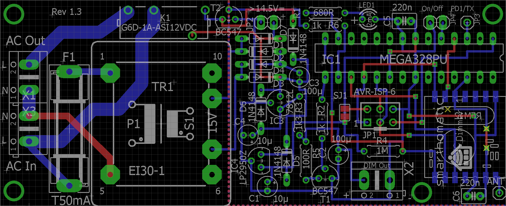
| 1 | PCB Dimmer |  |
|
| 6 | Diode 1N4148 | D1-D6 |  |
| 1 | Resistor 680R blue-gray-brown | R1 |  |
| 2 | Resistor 1k brown-black-red | R2, R6 |  |
| 1 | Resistor 1M brown-black-green | R4 |  |
| 1 | Resistor 1k3 0,1% brown-orange-black-brown | R3 |  |
| 1 | Resistor 100R 0,1% brown-black-black-black | R5 |  |
| 1 | IC holder | IC1 |  |
| 1 | Voltage regulator 7812L | IC3 |  |
| 1 | Voltage regulator LP2950Z | IC4 |  |
| 2 | Transistor BC547C | T1, T2 |  |
| 1 | LED 2mA | LED1 |  |
| 1 | Connector AVR ISP 6pin angled | JP1 |  |
| 3 | Connector 2pin | X1, X2, X3 |  |
| 1 | Connector 1 pin header (for serial TX debugging) | JP2, JP3 |  |
| 2 | Capacitor 10µF | C1, C4 |  |
| 2 | Capacitor 100µF | C2, C3 |  |
| 1 | IC ATMega328 | IC1 |  |
| 1 | Fuse holder | F1 |  |
| 1 | Fuse 50mA T | F1 |  |
| 1 | Relay G5LE (12V) | K1 |  |
| 1 | Transformer 12V | TR1 |  |
| 1 | Transceiver PCB RFM12B | IC2 |  |
| 1 | Antenna (82,2mm wire) |  |
Buildup of PCB
As always: start from flat to high. Go through the partlist and solder the parts from the top ones to the last ones.
For some parts, you have to consider something special:
- IC holder: Look at the notch and place it in the right direction.
- LED: Solder it to a wire if you want to place the PCB in a housing later. Read the instructions on how to solder the LED to a cable. The longer wire of the LED is +. It goes into the hole more in the middle of the PCB.
- ISP Connector: The notch points to the side of the PCB (towards the voltage regulator).
- Capacitors: The marked line is -. On the PCB, + is labelled.
- ATMega: Before inserting it, you may want to check the voltage levels when switching the power on. Pin7 should have VCC (3.3V) against pin8 (ground). If you have different voltages: don't panic, nothing is broken, nothing is fried. Search your error. To insert the ATMega, bend the pins at 90 degreed by placing the ATMega on the table and bending it carefully. Then insert it into the IC holder. Be sure that you are not charged with electricity (ESD!) when touching the IC pins.
- RFM12B: You should also check the voltages first before soldering the module. At the place for the radio module the pad beside the antenna and at the opposite side the third pad should read about 3.3 V. For soldering, read the RFM12B mounting instructions.
(Image directly loaded from external GitHub source. If it doesn't work, fix link in wiki!)
Bringing the device into operation
 Don't power the circuit immediately by the 230V transformer. It is highly recommended to first connect a DC power supply to JP2 at 14.5 to 20V. You can then safely set up and test everything without using dangerous high voltages.
Flashing the firmware
If you have a new ATMega where nothing is flashed onto, download a prebuilt binary package or build your own firmware. If you bought a hardware kit, the ATMega should already be flashed.
After flashing and switching the power on, the LED flashes several times. The relay stays off. If you switch the dimmer on with a switch at JP4 (near the LED), the relay should switch on.
Integrate it into a housing
describe it…