Table of Contents
Building up the Controller
Needed Parts and PCB
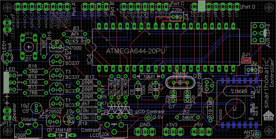
You need a PCB. You may use the layout from Github and etch it yourself / let it be produced at a factory creating PCBs.
Partlist (in buildup order)
You have to decide on the LEDs you want to use. Depending on the type, you have to use different resistors R13, R14, R16 for the LEDs. See the corresponding part in the RGB Dimmer description about recommended values.
Buildup of PCB
As always: start from flat to high. Go through the partlist and solder the parts from the top ones to the last ones.
For some parts, you have to consider something special:
- IC holder: Look at the notch and place it in the right direction.
- LED: Solder it to a wire if you want to place the PCB in a housing later. Read the instructions on how to solder the LED to a cable. The longer wire of the LED is +. It goes into the hole more in the middle of the PCB.
- ISP Connector: The notch points to the side of the PCB.
- 10 uF Capacitor: The marked line is -, which points to the mid of the PCB. On the PCB, + is labelled.
- ATMega: Before inserting it, you may want to check the voltage levels when switching the power on. Pin10 should have VCC (5V) against pin11 (ground). If you have different voltages: don't panic, nothing is broken, nothing is fried. Search your error. To insert the ATMega, bend the pins at 90 degreed by placing the ATMega on the table and bending it carefully. Then insert it into the IC holder. Be sure that you are not charged with electricity (ESD!) when touching the IC pins.
- RFM12B: You should also check the voltages first before soldering the module. At the place for the radio module the pad beside the antenna and at the opposite side the third pad should read about 3.3 V. For soldering, read the RFM12B mounting instructions.
(Image directly loaded from external GitHub source. If it doesn't work, fix link in wiki!)
Modification of PCB rev. 1.0
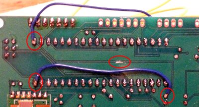
In the initial PCB, the blue LED channel is connected to PD7 (OC2A, pin21). To use the same code as for the RGB Dimmer, this needs to be rewired to PD6 (OC2B, pin20). Cut the connection at the bottom of the PCB and make the new connection with a wire.
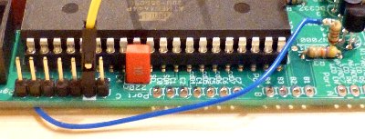
The status LED has to be rewired from initial PB2 (pin3) to PD7 (pin21), also to use the same code as in all other devices for the status LED. This can be done easiest by connecting the resistor R1 to a wire and connecting the wire to PD7.
In future PCB versions, this shall be changed in the schematic and layout.
To perform the modification, cut the PCB tracks on the marked positions and connect them to the other pins with patch cables.


