Table of Contents
Building up a Base Station (or Proxy)
Needed Parts and PCB
You need a PCB. You may use the layout from Github and etch it yourself or order the PCB or a complete kit.
The base station is designed to run 24/7 on 5V and to be connected to a PC, so you may prefer a stabilized 5V power supply, and not running on batteries. Any USB power supply will do well, and many mobile phone chargers are working at 5V.
Partlist (in buildup order)
| Amount | Part | Placing | Picture |
|---|---|---|---|
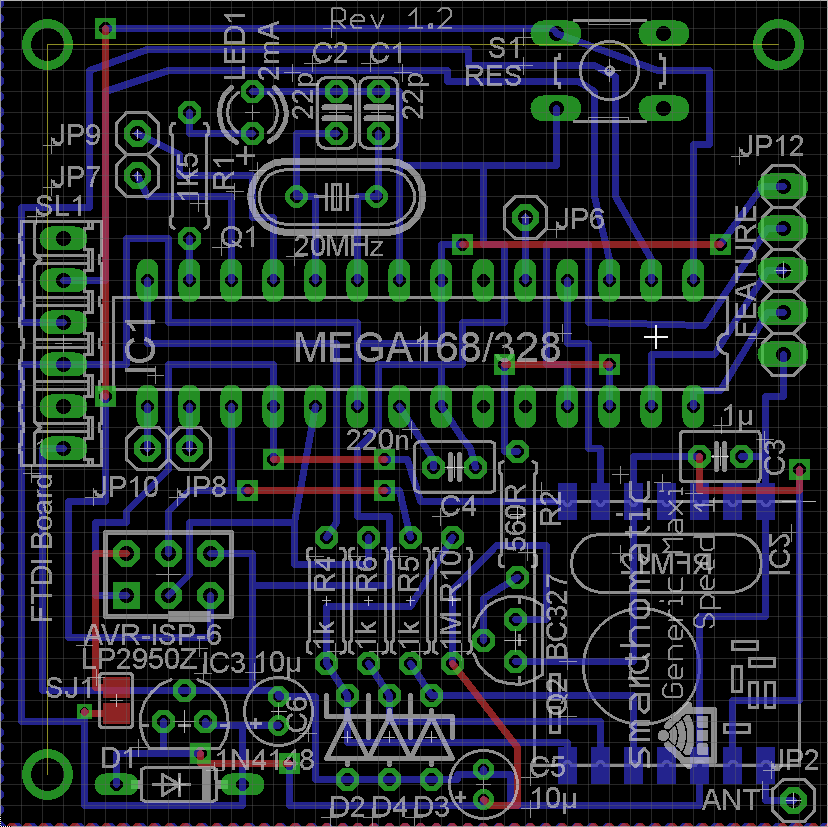
| 1 | PCB Generic Maxi Speed 1 |  |
|
| 1 | Diode 1N4148 | D1 |  |
| 3 | Zener Diode 3,3V | D2, D3, D4 |  |
| 1 | Resistor 1k5 brown-green-red | R1 |  |
| 3 | Resistor 1k brown-black-red | R4, R5, R6 |  |
| 1 | Resistor 1M brown-black-green | R10 |  |
| 1 | Quarz / Crystal 20 MHz | Q1 |  |
| 2 | Capacitor 22pF | C1, C2 |  |
| 1 | Button/Switch | S1 |  |
| 1 | IC holder | IC1 |  |
| 1 | Voltage regulator LP2950Z | IC3 |  |
| 1 | Transistor BC327 | Q2 |  |
| 1 | LED 2mA | LED1 |  |
| 1 | Connector AVR ISP 6pin | JP1 |  |
| 2 | Capacitor 1µF | C3 |  |
| 2 | Capacitor 10µF | C5, C6 |  |
| 1 | Capacitor 220nF (optional for ADC usage, not for base station) | C4 |  |
| 1 | IC ATMega328 | IC1 |  |
| 1 | Transceiver PCB RFM12B | IC2 |  |
| 1 | Antenna (82,2mm wire) | JP2 |  |
some jumpers and connectors for power, serial and maybe extra pins, at your opinion.
Optional:
- resistors 150k & 330k, for measuring the supply voltage. Obsolete for a base station, but you can connect them if you built something else with the Generix Maxi Speed PCB that runs on batteries.
Buildup of PCB
As always: start from flat to high. Go through the partlist and solder the parts from the top ones to the last ones.
For some parts, you have to consider something special:
- Diodes: Look at the marked ring. This has to match the line / the top of the arrow on the PCB.
- IC holder: Look at the notch and place it in the right direction.
- Voltage regulator: Make the soldering time of this IC short to not overheat it. Don't push it all the way down to the PCB and cut the wires. Just push the wires about 1 or 2 mm through the PCB, to prevent overheating while soldering.
- LED: Solder it to a wire if you want to place the PCB in a housing later. Read the instructions on how to solder the LED to a cable. The longer wire of the LED is +. It goes into the hole more in the middle of the PCB.
- ISP Connector: The notch points to the side of the PCB (towards the voltage regulator).
- 10 µF Capacitor: The marked line is -, which is more in the middle of the PCB for both capacitors. On the PCB, + is labelled.
- USB-to-serial connector: Either solder a 90 degree pin header here or some wires, which makes it easier to place the USB-to-serial PCB in a houseing. If using a pin header, make sure the shorter part is inserted into the SHC PCB. Ground (labelled on the USB-to-serial PCB) is in the middle of the SHC PCB.
- ATMega: Before inserting it, you may want to check the voltage levels when switching the power on. Pin7 should have VCC (5V) against pin8 (ground). If you have different voltages: don't panic, nothing is broken, nothing is fried. Search your error. To insert the ATMega, bend the pins at 90 degreed by placing the ATMega on the table and bending it carefully. Then insert it into the IC holder. Be sure that you are not charged with electricity (ESD!) when touching the IC pins.
- RFM12B: You should also check the voltages first before soldering the module. At the place for the radio module the pad beside the antenna and at the opposite side the third pad should read about 3.3V. For soldering, read the RFM12B mounting instructions.
- Antenna: After you solder the antenna, which might be a little bit longer at first, measure it's length and cut it exactly at 82.2mm.
(Image directly loaded from external GitHub source. If it doesn't work, fix link in wiki!)
Flashing the firmware
If you have a new ATMega where nothing is flashed onto, download a prebuilt binary package or build your own firmware. If you bought a hardware kit, the ATMega should already be flashed.
After flashing and switching the power on, your base station should start blinking the LED once a second.
Integrate it into a housing
This is an example how to integrate the electronics into a nice housing. Here a black plastic housing was used (Conrad, 2.15EUR). The left figure shows the planned arrangement of parts: The smarthomatic base-station pcb, the FTDI FT232RL based serial USB adapter and the LEDs. The housing contains 4 pins inside for screw mounting, but it was on the wrong place, so it was removed with a drill and a chisel. On the side wall the marks for the USB-port and the LEDs are visible. The third figure shows the final assembly, the second LED was omitted. All parts were fixed with hot glue.
 |  |
|---|---|
 |