

Features in Detail
Device IDs
A device ID identifies each SHC device and is programmed into the EEPROM. It is used as SenderID and ReceiverID when devices communicate with each other. A 12 bit value is used, allowing 4096 addresses and devices. The base station being a special device controlling other devices has always ID 0.
You are free to select any other ID for other devices. But it's recommended using ascending numbers for devices of the same type (e.g. temperature sensors with ID 20 to 29, power switches from 30 to 49). This makes it easier for you to keep an overview of the devices in use over time.
Note: If it's necessary to split up devices into subnets in the future, the 12 bits would allow this by using e.g. the first 4 bits as a network address and the last 8 bits as device ID. Currently, no subnet concept is defined though.
Encryption
One important design goal was security. All packets are encrypted with AES-256. Every device has one or more AES keys in the EEPROM for encoding and decoding packets. The first AES key is normally used for encryption of packets.
The Purpose of Encryption
- Anyone not knowing the key cannot read what was transmitted.
- Without knowing the content and the key, an attacker doesn't know how to create another valid packet, because simple duplicates are ignored.
Encryption Procedure
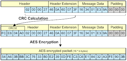
AES encryption of packets (byte counts are not correct and only for visualisation)
- Packet header, header extension, message data and padding bytes are stored in a buffer of the size 12 + 16 * x bytes.
- The CRC32 checksum is calculated and added to the beginning of the buffer.
- The complete packet, including CRC32 checksum, is encrypted using a specific key. The size is always a multiple of 16 bytes, which is the block size for AES.
Decryption Procedure after Reception
- If the size is not a multiple of 16 (the AES block size), it is ignored. Either a packet from a non SHC device was received, or the transmission was disturbed.
- The packet is decoded, first with AES key 1.
- The CRC32 is checked, which is included in the header.
- If the checksum is not correct, the package is assumed to be not correctly decrypted (wrong key). If available, the next AES key is used for decryption. The process continues at step 2.
- If the checksum is correct, the packet counter is checked. If it is higher than the last received packet counter from this device, the packet is finally accepted. The packet is ignored otherwise.
Contribution of the Packet Counter to Encryption
Each packet is valid only once. For this feature, the packet counter is increased for every new packet. This automatically makes the first AES encoded block (16 bytes) different every time. To ensure that further blocks are also different every time, cipher-block chaining (CBC) is used. This means that the encryption result of one block is used to encrypt the following block resulting in the complete message being different every time. This is important, because otherwise the meaning of packets could be guessed by identifying that some parts of some messages are the same every time.
Different AES Keys
An SHC network can use several different AES keys. This is useful to use one AES key in some of the less secured devices (e.g. an outdoor temperature sensor) and another AES key for devices at a secure place (indoor, e.g. your door lock and a wireless key device). If a device with one key is stolen and the key therefore compromised, it does not affect devices using other keys.
A device can have more than one AES key stored in its EEPROM to allow encryption and decryption of packets from devices with different keys. But this is mainly used for the base station. In this case, every AES key is used trying to decrypt an incoming packet. For communication with another device, the proper key has to be used.
Processing Time
AES encryption and decryption in a small microcontroller takes some time. If the device is runnning only at 1 MHz clock speed, it may take several hundred milliseconds to decode a 16 byte block. Longer messages may take a second or more. If several keys have to be used trying to decrypt a message, the duration multiplies by the number of keys in the worst case.
But this is not a problem. One second for encoding at a battery powered sensor running at 1 MHz is an insignificant delay for a status update sent only every 10 minutes. And the base station, which has to decode packets with different keys can run at 20 Mhz. Even when using many devices, the small amount of time used for communication and encryption is small compared to the available time.
A possibility to make the base station process many received packets in a short time would be to hand over the encrypted packets directly to the PC software that's controlling the base station and letting the PC handle the decryption. This idea was deliberately dropped because it increases the dependency to the controlling PC software dramatically.
Are you an encryption expert? If you find any design flaws in the encryption, please let me know!
Request Queue
The request queue is used to store requests in a device until its acknowledge is received. It is relevant that all requests to one receiver are sent strictly after one another (FIFO). Think of a switch where you send the command "all switches on", followed by "switch two off".
Because of the very limited amount of memory in the microcontrollers, the request queue is implemented with a queue matrix, which is used to map queue positions to request buffer slots. With this solution it is possible to store e.g. four requests for one receiver, or four requests for four different receivers with only four buffer slots in total.
Example
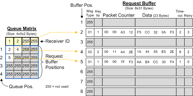
Queue Matrix and Request Buffer working together
In this picture, you can see two requests stored for receiver ID 1 and one request stored for receiver ID 2. These receiver IDs are at the top of the queue matrix, a 2-dimensional array. Queue position 1 for receiver ID 1 points to request buffer position 2. This means that the first request to be sent out to receiver ID 1 is stored here. The retry count of this request is already at 3, so 3 attempts were made sending the request. The timeout value is currently 2, so the next retry will be made in 2 seconds. AES key number 1 will be used for encryption.
Cyclic Processing
Each new request is stored in the request buffer and referenced through the queue matrix first. If a queue for the given receiver already exists, the new request is stored as the last element in the queue for this receiver (at least if the queue is not full and buffer slots are available).
Every second the sending device checks the top element of each queue in the queue matrix. If the current timeout for a request is reached, the request is sent and the timeout is increased. The initial value for timeouts is 1, so a new request is sent directly at the first check. Only a limited amount of retries is done to not block the queue infinitely. If the maximum retry count if reached, the request is deleted from the queue after sending it the last time.
If an acknowledge is received at any time, the device ID of the sending device and the packet counter of the acknowledge are compared to the first packets in the queues. If one matches, the request is deleted from the queue and the other elements are moving one position up in the queue.
Battery Level Monitoring
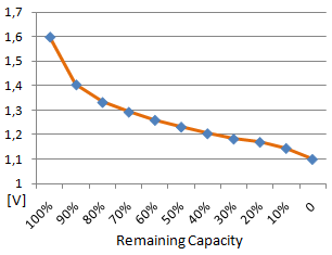
Battery voltage of alkaline cell with
assumed lowest voltage of 1.1V
An important feature is the measurement and transmission of the current battery status. Every device which is battery powered (and most are) shouldn't require checking the battery status manually. Imagine you have 20 devices, each with batteries of a different age. It would be unnerving not to forget to replace the batteries before they are empty.
Battery level monitoring in SHC devices works as follows: the voltage is measured a few times before an average is calculated that is used as the basis. A voltage table with values from 0 to 100% capacity in 10% steps is used to interpolate the remaining battery capacity. This value is transferred with a normal status packet as a percentage.
Usually 1.1V is used as lowest possible voltage for a device powered by two battery cells. This is because the lowest allowed voltage for the RFM12 transceiver is 2.2V.
Transceiver Watchdog Function
To recover in case a RFM12 transceiver is stuck and not receiving or sending any packets anymore (which happens over time to almost every module which runs in receiving mode), there are several watchdog functions implemented to recover. Note that all of these are not necessary when a device only sends data, like the Environment Sensor.
The firmware detects three cases with increasing criticality as follows:
1) Reset after Dynamic Transceiver Watchdog Timeout
When the TransceiverWatchdogTimeout is set in E2P, the dynamic transceiver watchdog function is also activated. The device logs how much time passes between received packets. It remembers the 10 largest periods with a granularity of 5 seconds for up to 3000 incoming packets. When at least 150 such offsets are received after powering up the device, and when the time passed since the last valid packet is twice this dynamically calculated maximum, the firmware will reset the RFM12 and also the complete ATMega, restart and reinitialize. It will send a HardwareError packet with ErrorCode TransceiverDynamicWatchdogReset to inform about it. By the dynamic calculation of the timeout, this function tries to detect the error situation early, to have the device under control again as early as possible. With remembering the seldomly happening largest periods for up to 3000 incoming packets, it is ensured that they're valid as maximum for a long time, usually long enough until they appear again. If not, another value is likely to be not much lower. If values would be stored only for a short time, then it would be likely that the seldomly happening long periods between packets (without an RFM12 problem) would already trigger the watchdog. On the other hand, the device still adjusts the detected maximum over time (usually some hours to over a day), to consider changing conditions (depending on other devices in range).
Note that only packets that can be successfully decoded and have a correct CRC checksum are considered to avoid that received garbage data (from non-smarthomatic 868 MHz devices) interferes the detection.
2) Reset after Fixed Transceiver Watchdog Timeout
If no packet is received after the statically configured TransceiverWatchdogTimeout, the firmware will also do the same reset as above. This timeout value can be chosen a bit larger and is meant to ensure the reset in case the dynamic timeout would not work, e.g. becaue the dynamic values would go up slowly and it would not be an immediate loss of the reception functionality. This timeout shall be longer than the maximum expected time between decodable packets. If e.g. several Environment Sensors using the same AES key send every 7 minutes, it's safe to choose 8 minutes here, because it's absolutely likely that at least one of their packets can be received in this time frame. The device will send a HardwareError packet with ErrorCode TransceiverWatchdogReset if this timeout occurs.
3) ATMega Watchdog Reset after Firmware Freeze
If the main loop of the firmware hangs and therefore also the above functions don't work (e.g. because of a communication hang between ATMega and RFM12 module or any other issue), the device makes a RFM12 and ATMega reset as well. In this case, a HardwareError packet with ErrorCode WatchdogReset is sent after restart. This case should never happen and is meant for unexpected errors (in contrast to the above cases which are expected).
RC Oscillator Calibration Function
Most of the time, the easiest solution for the microcontroller's clock source is to use the internal RC oscillator. This oscillator is not very accurate (+/- 10% without calibration). Usually, a device doesn't need a more accurate clock, because the RFM12 module has its own accurate crystal and has the ability to wake up the microcontroller at given time intervals. So if you want to have let's say sensor data from a device exactly every ten minutes, this is easily possible using the wake up function from the RFM12.
If the microcontroller itself needs an accurate clock (within +/- 1% accuracy), the RC oscillator calibration function can be used. The used Atmel microcontrollers have a register that changes the RC oscillator speed when a different value is written to it. To make this function available more easily, you can configure the change by writing the EEPROM value OSCCAL_MODE. (OSCCAL is the name of the register. It stands for OSCillator CALibration register.)
This byte has the following meaning:
- 00: don't use OSCCAL calibration
- FF: OSCCAL measurement mode: The LED blinks every 60s.
- 01..FE: The speed is adjusted. If the value is X, the speed is adjusted by (X - 128) promille.
Example: Setting the value to 138 adjusts the speed by (X - 128) per mille = +1%.
For calibration, you set the value to FF first and measure the time between two LED blinks. After calculating the needed speedup / slowdown to meet 60s, you set the desired value in EEPROM, so the clock speed changes accordingly.
EEPROM Compatibility Check
Malfunction should be avoided for the case that a wrong EEPROM content is written. This situation is detected by comparing the DeviceType byte with a value compiled into the firmware. This cannot prevent you from writing wrong values to the EEPROM, but if you handle several EEPROM files for all your devices and write one from a different device type to a device, this can be detected at least. In case of this error, the LED blinks infinitely and the device does not do anything else.
Used Libraries
The following libraries and functions from other contributors were used in the core part:
- RFM12: The rfm12lib from Peter Fuhrmann, Hans-Gert Dahmen and Soeren Heisrath, http://www.das-labor.org.
- AES-256: An implementation from Ilya O. Levin, http://www.literatecode.com. Functions for direct encoding of a byte array and for the CBC mode were added by me (Uwe Freese).
- CRC32: An implementation from K.Moraw, http://www.helitron.de.
Other libraries used for specific devices are listed in their description.