soil_moisture_meter
This is an old revision of the document!
Table of Contents
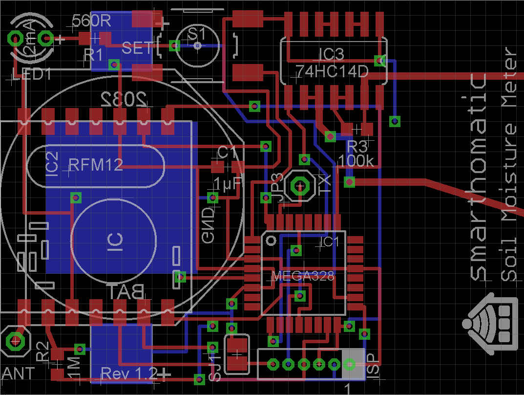
Building up a Soil Moisture Meter
Needed Parts and PCB
Partlist (in buildup order)
| Amount | Part | Placing | Picture |
|---|---|---|---|
| 1 | PCB Soil Moisture Meter |  |
|
| 1 | Battery holder CR2032 | BAT |  |
| 1 | Capacitor 1µF | C1 |  |
| 1 | IC ATMega328 TQFP | IC1 |  |
| 1 | Transceiver PCB RFM12B | IC2 |  |
| 1 | IC 74HC14D | IC3 |  |
| 1 | Connector AVR Mini ISP 6pin | JP1 |  |
| 1 | Connector pin header (for serial TX debugging etc.) | JP3 |  |
| 1 | Antenna (82,2mm wire) | ANT |  |
| 1 | LED 2mA | LED1 |  |
| 1 | Resistor 220R | R1, R6 |  |
| 1 | Resistor 1M | R4 | |
| 1 | Resistor 100k | R5 | |
| 1 | Switch | S1 |  |
Buildup of PCB
Since this is a SMD PCB, you usually don't solder the parts with a soldering iron manually. Instead, you apply soldering paste to the PCB, place the parts on it and heat everything in a special oven. Please search in the internet on how to do that. You could also help writing a short “best practice” howto in this wiki.
- The first step is to solder (with soldering paste) all the SMD components, which is everything except the RFM12B module, the two pin connectors, LED and antenna.
- Measure with a continuity checker if there are any short circuits and remove them carefully. Especially check the pins of the ATMega.
- Solder the ISP connector and debug TX pin.
- You should flash the device now and see if everything works.
- Measuring of the idle power consumption is helpful to make sure there are no high impedance short circuits somewhere. (Note: Firmware has to be changed to allow that without connected RFM module.)
- Solder the RFM12B, LED and antenna with a soldering iron as usual.
(Image directly loaded from external GitHub source. If it doesn't work, fix link in wiki!)
Flashing the firmware
If you have a new ATMega where nothing is flashed onto, download a prebuilt binary package or build your own firmware. If you bought a hardware kit, the ATMega should already be flashed.
Integrate it into a housing
describe it…
soil_moisture_meter.1415285515.txt.gz · Last modified: 2014/11/06 15:51 by breaker27