This is an old revision of the document!
Table of Contents
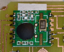
Prepare the solder pins
Apply a tiny bit of solder to the pins of the RFM12B transceiver before you solder it to the PCB of the smarthomatic device. You don't need to do this with every pin, but only with the ones that will be connected later on. See the picture below.
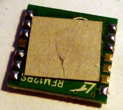
Applying Paperboard / Isolation
The RFM12B transceiver has some places which are not isolated. As soon as you use a PCB which is soldered by yourself and has no isolation as well, there has to be an isolation between the SHC device's PCB and the RFM12 module.
You can use a piece of paper or plastic for isolation, or glue the RFM12B module with a little bit of hot glue to the PCB. This will also result in a little isolation space.
Please note that the paperboard isolation may not be optimal if the device is used in moist conditions. I have no long term experience using the paperboard as isolation.
Soldering
The gold plated connections from the RFM12 are coated with a little tin-solder first.
After gluing the transceiver to the PCB, you can solder the connections to the SHC PCB easily.