This is an old revision of the document!
Table of Contents
Modification of Honeywell HR25 thermostat
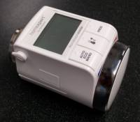 The Honeywell Rondostat HR25 is an electronically programmable thermostat for radiators.
For integration into a smarthomatic network it needs a RFM12B transmitter and a new firmware.
To keep the programming scheme similar to other smarthomatic devices, an ISP connector is added for easy flashing.
The housing is hacker friendly, it opens without the risk of breaking it.
The electronics is based on an ATmega329P processor.
Initial idea is based on the development done for the HR20 thermostat, the OpenHR20 project.
Needed Parts
You need a Honeywell Rondostat HR25 thermostat. It costs about 30,-EUR, but used items go away for sometimes as low as 15,-EUR at ebay/amazon.
Partlist (in buildup order)
| Amount | Part | Picture |
|---|---|---|
| 1 | Honeywell HR20/HR25 thermostat |  |
| 1 | Connector ISP 2×3 pin |  |
| 1 | Transceiver PCB RFM12B |  |
| 1 | Antenna (82,2mm wire) |  |
some thin short flexible wires to connect ISP and RFM12B with the PCB of the HR25 thermostat.
Hardware Modification
Open the HR25 thermostat
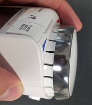
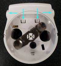
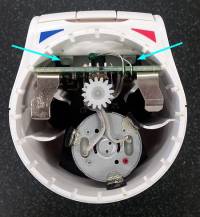
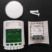
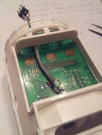
To open the housing, lift the turn wheel with a flat piece of plastic to avoid scratches. It snaps off and you can look into the device (Figure 2). Then remove the lock pins using the same plastic lever (see Figure 3, arrows to left and right). After pushing the 4 notches (see arrows in figure 5), the housing snaps open. Unscrew the PCB (just 1 screw) and slide it out. Sometimes the mounting contact is stuck on the housing.
Integrate the additional electronics into the housing
If a 2×3 PCB-pin connector is used for ISP, it is possible to hide it behind the turn wheel. This way it it easy accessible for reprogramming and there is little to no need to modify the housing or PCB1).
The RFM12B fits well inside the thermostat housing between display and PCB.
Wiring of ISP and RFM12B
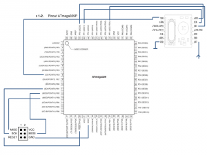
The ISP (tested, works) and RFM12B (not tested yet) are connected as follows as shown on the right. You will need a fine solder tip. The best is to solder the wires to the back side (looking up to the display).
Flashing the firmware
to do
Links
Other resources dealing with hacking of HR20/HR25 thermostats:

