Table of Contents
Building up an Environment Sensor
Needed Parts and PCB
You need a PCB. You may use the layout from Github and etch it yourself or order the PCB or a complete kit.
The envsensor is designed to run 24/7 on two alcaline batteries with an estimated battery lifetime of > 5 years.
Partlist (in buildup order)
| Amount | Part | Placing | Picture |
|---|---|---|---|
| 1 | PCB Generic Midi 1 |  |
|
| 1 | Resistor 560R green-blue-brown | R1 |  |
| 1 | Resistor 150k 0,1% brown-green-black | R2 (firmware < 0.9) (PCB < 1.4) |  |
| 1 | Resistor 330k 0,1% orange-orange-black | R3 (firmware < 0.9) (PCB < 1.4) |  |
| 1 | Resistor 1M brown-black-green | R4 |  |
| 1 | Resistor 100k brown-black-yellow | R5 (for light sensor) |  |
| 1 | Resistor 10k brown-black-orange | R6 (for SHT15), R7 + R8 (for I2C) |  |
| 1 | Resistor 4k7 yellow-violet-red | R9 (for 1-wire) |  |
| 1 | IC holder | IC1 |  |
| 1 | LED 2mA | LED1 |  |
| 1 | Connector AVR ISP 6pin | JP1 |  |
| 1 | Connector 1 pin header (for serial TX) | PD1 |  |
| 1 | Capacitor 10µF | C3 |  |
| 1 | Battery Holder 2xAAA |  |
|
| 1 | IC ATMega328 | IC1 |  |
| 1 | Transceiver PCB RFM12B | IC2 |  |
| 1 | Antenna (82,2mm wire) |  |
maybe extra pins, at your opinion.
Buildup of PCB
As always: start from flat to high. Go through the partlist and solder the parts from the top ones to the last ones.
For some parts, you have to consider something special:
- IC holder: Look at the notch and place it in the right direction.
- LED: Solder it to a wire if you want to place the PCB in a housing later. Read the instructions on how to solder the LED to a cable. The longer wire of the LED is +. It goes into the hole more in the middle of the PCB.
- ISP Connector: The notch points to the side of the PCB.
- 10 uF Capacitor: The marked line is -, which points to the LED. On the PCB, + is labelled.
- R7+R8: These pull-up resistors are for I2C use. You can leave them out if you don't use I2C.
- Battery holder: + is the pin towards the middle of the PCB.
- ATMega: Before inserting it, you may want to check the voltage levels when switching the power on. Pin7 should have VCC (3V) against pin8 (ground). If you have different voltages: don't panic, nothing is broken, nothing is fried. Search your error. To insert the ATMega, bend the pins at 90 degreed by placing the ATMega on the table and bending it carefully. Then insert it into the IC holder. Be sure that you are not charged with electricity (ESD!) when touching the IC pins.
- RFM12B: You should also check the voltages first before soldering the module. At the place for the radio module the pad beside the antenna and at the opposite side the third pad should read about 3.3 V. For soldering, read the RFM12B mounting instructions.

(Image directly loaded from external GitHub source. If it doesn't work, fix link in wiki!)
Flashing the firmware
If you have a new ATMega where nothing is flashed onto, download a prebuilt binary package or build your own firmware. If you bought a hardware kit, the ATMega should already be flashed.
You can leave the batteries inserted all the time, no matter if you're currently flashing or using the device.
To make a “reset”, take one battery shortly out of its holder.
After flashing and switching the power on, your temp sensor should blink quickly for some seconds. After that, it only flashes shortly once whenever a temperature data packet is sent (>5 min).
Improve idle power consumption (PCB Rev. < 1.2)
 Battery voltage and brightness are measured using two voltage divisors each consisting of two resistors. The idle power consumption can be improved (down to about 21µA) by connecting the one end of them (see both left red ovals at R3 and R5) to PB6 (pin 9, the other red oval), which is only switched on when the device is actively measuring.
You only need this modification with a PCB version Rev. < 1.2, where the resistors were not connected to the I/O pins. The advantage in power consumption is not so big if you don't have a photocell connected. To use this feature, you need also a firmware >= v0.7.0 or develop build from 06/17/2014 or later.
<clear>
Connecting specific sensors
Please read about the supported sensors at the envsensor description. Below, you'll find assembly instructions.
Even if the SHT15 uses partly the same pins as the I2C sensors, they can be connected and used in parallel!
Connect a button or switch
You can use any of the available I/O pins as a digital input. You have different options regarding the pull-up resistor and therefore the power consumption. The behaviour can be configured with the EEPROM editor.
- If you want to measure the state only cyclic after the RFM12 wake-up timeout, it's recommended to use the internal pull-up resistor and connect the button / switch against ground. The pull-up is only switched on a very short time when the device is on and therefore draws much less power than connecting a physical pull-up which is connected all the time.
- If you want to detect the botton / switch / pin state immediately, you need some sort of permanent pull-up resistor (assuming the button/… is connected against ground again). Please note that the pull-up resistor only draws current if the button/… is currently active (pulling the level to low).
- If you use the internal resistor with its resistance of around 22 kOhm, it would draw about 135µA, which is a lot. This is only recommended if you power your device with a power supply (not batteries).
- The second option is to connect an external (physical) pull-up resistor of 1 MOhm to 10 MOhm. One 1 MOhm pull-up (for one I/O pin) would draw around 3µA (at 3V battery voltage), so this is also noticeable compared to the sleep power consumption of around 1,2µA. Depending on your batteries, amount of I/O pins used as digital input and the percentage of the pin being pulled down by the button/…, you may try a risistor with a higher value like 10 MOhm.
Connect a SHT15
The mapping between SHT15 and Generic Midi PCB was different before firmware V0.6.0. If you want to use a firmware < 0.6.0, connect the SCK pin of the SHT15 with PC4 instead of PC2. The images below show how to connect the SHT15 using a current firmware.
PCB Rev. >= 1.2
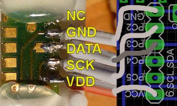 Connect the SHT15 sensor to a ribbon cable by soldering the four pins shown on the picture. The SHT15 is very sensitive to heat. I suggest soldering one pin, wait a minute or two and then solder the next!
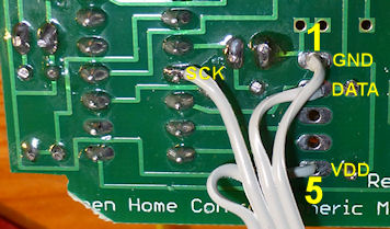
Solder the other end of the wires to the PCB. The picture is from the top side of the PCB. The border of the PCB is at the bottom of the picture.
<clear>
PCB Rev. <= 1.1
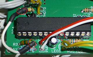
 If you have an older PCB version you have to patch the SCK wire to the PC2 pin on the bottom side of the PCB. It is the fourth pin of the ATMega counting from the PCB border.
If you look at the back of the PCB, you have to solder the wires as shown on the picture.
<clear>
Connect I2C sensors
 The pin layout for all I2C sensors in general is like shown here. Besides power and ground, they use a clock (SCL) and a data (SDA) line.
<clear>
Connect a SHT21 / SHT25
You can connect these sensors either the same way as the SHT15 (with the Sensirion specific protocol) or connect it as a I2C device. Configure the E2P accordingly.
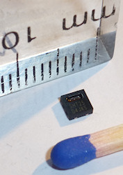
In principle, you can solder the sensor directly to cables. But the sensor is very tiny, so you should have some experience when trying to do that. Make sure to solder only one cable at a time and let the solder cool off to not overheat the sensor!
I recommend to mount the sensor + cables to something to make sure the solder joints don't break off.

<clear>
Connect a DS7505
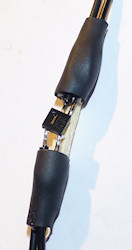
 I glued the DS7505 temperature sensor to a breadboard and connected wires to it.
If you want to connect other I2C sensors, you can wire them in parallel to the DS7505 as I did with a BMP085. That's why you can see two pairs of wires in the picture.
<clear>
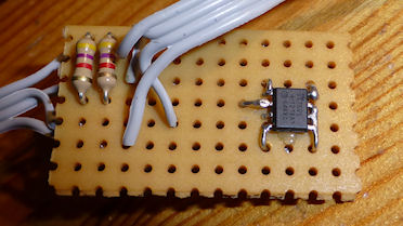
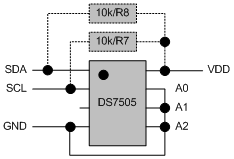 The pins have to be wired as shown here. You need 4k7/10k pull-up resistors as specified by the I2C standard. If you have a Generic Midi PCB Rev. 1.1 and up, just solder R7+R8 to the PCB. If you have an older PCB revision, you have to solder the resistors as shown in the picture.
<clear>
Connect a DHT11
describe it …
The four pins of the DHT11 are GND, Unused, DATA and VCC. Connect DATA to PC2. The sensor works when EnvSensor is powered by two AA batteries (90 Percent charge).
<clear>
Connect a BMP085
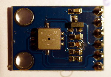 A BMP085 barometric pressure sensor is often available on small PCB. You can connect the pins (VCC, GND, SDA, SCL) the same way as described above for the DS7505.
<clear>
A BMP085 barometric pressure sensor is often available on small PCB. You can connect the pins (VCC, GND, SDA, SCL) the same way as described above for the DS7505.
<clear>
Connect a SRF02
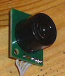 The SRF02 can be connected just like other I2C sensors to SDA, SCL, GND and VCC. Please note that the SRF02 needs 5V input voltage.
<clear>
You have two options for the power supply:
- Use a 5V power supply. Connect the 5V to the SRF02 and create 3V/3.3V for the SHC PCB with a simple voltage regulator (7803).
- Use two batteries and produce the 5V for the SRF02 with a step-up voltage regulator (see below).
Connect the voltage converter (for SRF02)
First you have to solder a small transistor circuit to power the voltage regulator. This is because the input current of the regulator is about 20mA at the low battery voltage used (SRF02: ~4,5 mA at 5V). The I/O pins of the ATMega328 can't produce this amount of current (at 2-3V).


As a voltage converter, I found this nice model at eBay for less than 2 EUR. It produces 5V and works with a minimum input voltage of 1V. It draws 0.25 mA when idle.


You should use at least AA cells for the environment sensor when using the SRF02 and the voltage converter, because one SRF02 measurement takes about 0.015 mAh, which results in ~800 days battery lifetime at AA cells (2800 mAh) when you make one measurement every 7 minutes.
Integrate it into a housing
describe it…