This is an old revision of the document!
Table of Contents
Needed Parts and PCB
You need a PCB. You may use the layout from Github and etch it yourself or order the PCB or a complete kit.
The base station is designed to run 24/7 on 5V and to be connected to a PC, so you may prefer a stabilized 5V power supply, and not running on batteries. Any USB power supply will do well, and many mobile phone chargers are working at 5V.
Partlist (in buildup order)
| Amount | Part | Placing | Picture |
|---|---|---|---|
| 1 | PCB Generic Maxi Speed 1 |  |
|
| 1 | Diode 1N4148 | D1 |  |
| 3 | Zener Diode 3,3V | D2, D3, D4 |  |
| 1 | Resistor 1k5 brown-green-red | R1 |  |
| 3 | Resistor 1k brown-black-red | R4, R5, R6 |  |
| 1 | Resistor 1M brown-black-green | R10 |  |
| 1 | Quarz / Crystal 20 MHz | Q1 |  |
| 2 | Capacitor 22pF | C1, C2 |  |
| 1 | Button/Switch | S1 |  |
| 1 | IC holder | IC1 |  |
| 1 | Voltage regulator LP2950Z | IC3 |  |
| 1 | LED 2mA | LED1 |  |
| 1 | Connector AVR ISP 6pin | JP1 |  |
| 2 | Capacitor 10uF | C5, C6 |  |
| 1 | IC ATMega328 | IC1 |  |
| 1 | Transceiver PCB RFM12B | IC2 |  |
some jumpers and connectors for power, serial, ISP and maybe extra pins, at your opinion.
Optional:
- resistors 150k & 330k, for measuring the supply voltage. Obsolete for a base station, but you can connect them if you built something else with the Generix Maxi Speed PCB that runs on batteries.
Buildup of PCB
As always: start from flat to high. Solder the wires first, then the resistors, diodes, condensators, the µC socket, the crystal. At the end solder the connectors, the voltage regulator and the LED. Diodes and tantalum condensators have a pin marked with a ring or a “+” printed on it. The direction matters, so when soldering them, take a look at the placing picture below. Don't solder the radio module, and don't push the µC into the socket. Connect the 5V power supply, and check if the right voltages are at the µC socket and at the radio module pads.
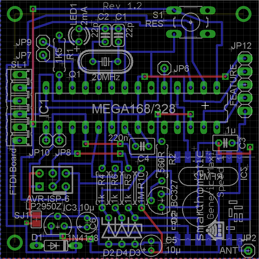 (Image directly loaded from external GitHub source. If it doesn't work, fix link in wiki!)
Connect the black test wire to the ground, f.ex. at the first pin of the serial port. The third pin should read approx. 5V, and the pins 6 & 21 of the µC socket should be 5V, too. At the place for the radio module the pad beside the antenna and at the opposite side the third pad should read about 3.3 V.
If you have different voltages: don't panic, nothing is broken, nothing is fried. Search your error.
If you get the correct voltages, solder the radio module in place. Remember to put a small isolation, maybe a small plastic part, between the base station PCB and the radio module, because they both are unisolated. Push the µC into the socket.
Flashing the firmware
If you have a new ATMega where nothing is flashed onto, download a prebuilt binary package or compile your firmware as described in xx. If you bought a hardware kit, the ATMega should already be flashed.
After flashing and switching the power on, your base station should start blinking the LED once a second.
Integrate it into a housing
describe it…