Table of Contents
Building up a Soil Moisture Meter
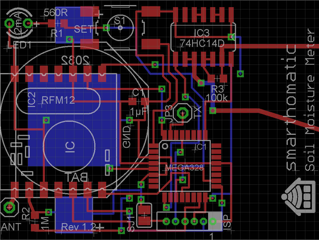
Needed Parts and PCB
Partlist (in buildup order)
| Amount | Part | Placing | Picture |
|---|---|---|---|
| 1 | PCB Soil Moisture Meter |  |
|
| 1 | Battery holder CR2032 | BAT |  |
| 1 | Capacitor 1µF | C1 |  |
| 1 | IC ATMega328 TQFP | IC1 |  |
| 1 | Transceiver PCB RFM12B | IC2 |  |
| 1 | IC 74HC14D | IC3 |  |
| 1 | Connector AVR Mini ISP 6pin | JP1 |  |
| 1 | Connector pin header (for serial TX debugging etc.) | JP3 |  |
| 1 | Antenna (82,2mm wire) | ANT |  |
| 1 | LED 2mA | LED1 |  |
| 1 | Resistor 560R | R1 |  |
| 1 | Resistor 1M | R2 | |
| 1 | Resistor 100k | R3 | |
| 1 | Button | S1 |  |
Buildup of PCB
Since this is a SMD PCB, you usually don't solder the parts with a soldering iron manually. Instead, you apply soldering paste to the PCB, place the parts on it and heat everything in a special oven. Please search in the internet on how to do that. You could also help writing a short “best practice” howto in this wiki.
- The first step is to solder (with soldering paste) all the SMD components, which is everything except the RFM12B module, the two pin connectors, LED and antenna.
- Measure with a continuity checker if there are any short circuits and remove them carefully. Especially check the pins of the ATMega.
- Solder the LED and ISP connector.
- Flash the device.
- Now connect a multimeter to check the power consumption. Press the button when the device starts up. The device will blink some seconds very fast and then go to power down mode. The device should draw only ~0.1µA. If the current is much higher, you may have a short circuit somewhere.
- Solder the debug TX pin, the RFM12B module and antenna with a soldering iron as usual.
- Switch on the device and check power consumption again. With connected RFM12, it should now be ~1.7µA.
(Image directly loaded from external GitHub source. If it doesn't work, fix link in wiki!)
Flashing the firmware
If you have a new ATMega where nothing is flashed onto, download a prebuilt binary package or build your own firmware. If you bought a hardware kit, the ATMega should already be flashed.
Integrate it into a housing
describe it…