controller
This is an old revision of the document!
Table of Contents
Building up the Controller
Needed Parts and PCB
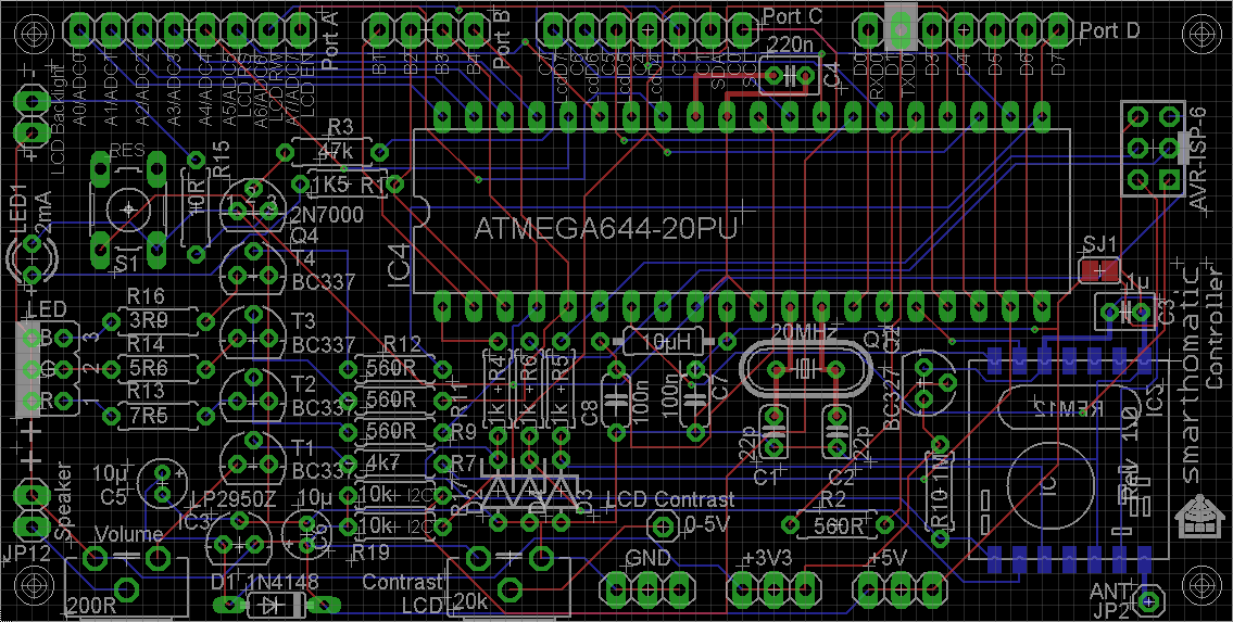
You need a PCB. You may use the layout from Github and etch it yourself / let it be produced at a factory creating PCBs.
Partlist (in buildup order)
| Amount | Part | Placing | Picture |
|---|---|---|---|
| 1 | PCB Controller |  |
|
| 1 | Diode 1N4148 | D1 |  |
| 3 | Zener Diode 3,3V | D2, D3, D4 |  |
| 1 | Resistor 1k5 brown-green-red | R1 |  |
| 4 | Resistor 560R green-blue-brown | R2, R9, R11, R12 |  |
| 1 | Resistor 47k XXXXXXXXXXXXXXXXX | R3 |  |
| 3 | Resistor 1k brown-black-red | R4, R5, R6 |  |
| 1 | Resistor 4k7 yellow-violet-red | R7 |  |
| 1 | Resistor 1M brown-black-green | R10 |  |
| 1 | Resistor 3R9 XXXXXXXXXXXXXXXXX | R16 |  |
| 2 | Resistor 10k brown-black-red | R17, R19 |  |
| 1 | Inductor 10µH | L1 |  |
| 1 | Quarz / Crystal 20 MHz | Q1 |  |
| 2 | Capacitor 22pF | C1, C2 |  |
| 1 | Capacitor 1µF | C3 |  |
| 1 | Capacitor 10µF | C5, C6 |  |
| 2 | Capacitor 100nF | C7, C8 |  |
| 1 | Capacitor 220nF | C4 |  |
| 1 | Button/Switch | S1 |  |
| 4 | Transistor BC337 | T1-T4 |  |
| 1 | Transistor BC327 | Q2 |  |
| 1 | FET Transistor 2N7000 | Q4 |  |
| 1 | Voltage regulator LP2950Z | IC3 |  |
| 1 | Trimmer Potentiometer 200R | R8 |  |
| 1 | Trimmer Potentiometer 20k | R18 |  |
| 1 | IC holder | IC4 |  |
| 1 | IC ATMega644-20PU | IC4 |  |
| 1 | Transceiver PCB RFM12B | IC2 |  |
| 1 | Antenna (82,2mm wire) | JP2 |  |
| 1 | LED 2mA | LED1/JP13 |  |
| 1 | Connector AVR ISP 6pin | JP1 |  |
You have to decide on the LEDs you want to use. Depending on the type, you have to use different resistors R13, R14, R15 for the LEDs. See the corresponding part in the RGB Dimmer description about recommended values.
Buildup of PCB
As always: start from flat to high. Go through the partlist and solder the parts from the top ones to the last ones.
For some parts, you have to consider something special:
- IC holder: Look at the notch and place it in the right direction.
- LED: Solder it to a wire if you want to place the PCB in a housing later. Read the instructions on how to solder the LED to a cable. The longer wire of the LED is +. It goes into the hole more in the middle of the PCB.
- ISP Connector: The notch points to the side of the PCB.
- 10 uF Capacitor: The marked line is -, which points to the mid of the PCB. On the PCB, + is labelled.
- ATMega: Before inserting it, you may want to check the voltage levels when switching the power on. Pin10 should have VCC (5V) against pin11 (ground). If you have different voltages: don't panic, nothing is broken, nothing is fried. Search your error. To insert the ATMega, bend the pins at 90 degreed by placing the ATMega on the table and bending it carefully. Then insert it into the IC holder. Be sure that you are not charged with electricity (ESD!) when touching the IC pins.
- RFM12B: You should also check the voltages first before soldering the module. At the place for the radio module the pad beside the antenna and at the opposite side the third pad should read about 3.3 V. For soldering, read the RFM12B mounting instructions.
(Image directly loaded from external GitHub source. If it doesn't work, fix link in wiki!)
controller.1677697559.txt.gz · Last modified: 2023/03/01 20:05 by breaker27