

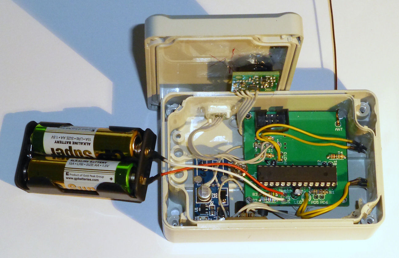
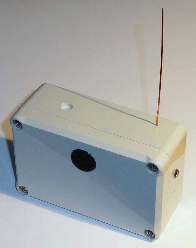
Environment Sensor
Purpose
The environment sensor is a multi purpose device that can measure temperature, humidity and other environmental values and broadcasts it every few minutes. Measuring this data in several rooms and outdoors provides basic data that can be used to control heating, windows or air humidifiers. Depending on how you integrate SHC in your infrastructure, you can show the current or historical values on a display or in a web application.
Supported Sensors
| Part | Type | Range | Accuracy | Long term drift | Supply Voltage | Protocol | Application, Remarks |
|---|---|---|---|---|---|---|---|
| SHT15 | Temperature | -40..123.8°C | max. ± 0.3°C @ 25°C, max. ± 1°C @ -20..65°C | max. 0.04°C / year | 2.4..5.5V | device specific | Temp sensor with integrated humidity sensor. Relatively easy to solder. |
| Humidity | 0..100% RH | max. ± 2% RH @ 10..90% RH | max. 0.5% RH / year | ||||
| SHT25 | Temperature | -40..125°C | max. ± 0.4°C @ 25°C, max. ± 0.7°C @ -20..80°C | max. 0.04°C / year | 2.1..3.6V | I2C and SHT15 protocol | Temp sensor with integrated humidity sensor. Hard to solder, because it is tiny (3x3mm). Better long term stability and voltage requirements than SHT15. |
| Humidity | 0..100% RH | max. ± 2% RH @ 10..90% RH | max. 0.25% RH / year | ||||
| SHT21 | Temperature | -40..125°C | max. ± 0.4°C @ 25°C, max. ± 0.7°C @ -20..80°C | max. 0.04°C / year | 2.1..3.6V | I2C and SHT15 protocol | Temp sensor with integrated humidity sensor. Hard to solder, because it is tiny (3x3mm). Less accurate than SHT25. |
| Humidity | 0..100% RH | max. ± 3% RH @ 10..90% RH | max. 0.5% RH / year | ||||
| HTU21D | Temperature | -40..125°C | max. ± 0.3°C @ 25°C, max. ± 0.85°C @ -20..65°C | max. 0.04°C / year | 1.5..3.6V | I2C | Cheap temp sensor with integrated humidity sensor. Compatible to SHT2x, but less accurate. |
| Humidity | 0..100% RH | max. ± 3% RH @ 20..80% RH | max. 0.5% RH / year | ||||
| DS7505 | Temperature | -55..125°C | ± 0.5°C @ 0..70°C Range | ? | 1.7..3.7V | I2C | cheap temp sensor |
| Photoresistor | Brightness | - | - | - | anything | A/D | detect if it's dark (raining / clouds), the sun rises etc. |
| BMP085 | Barometric Pressure | 300..1100 hPa | ± 0.5 hPa @ 0..65°C | max. 1 hPa / year | 1.8..3.6V | I2C | barometer (temperature reading is very inaccurate) |
| Temperature | -40..85°C | max. ± 2°C @ 0..65°C | ? | ||||
| DS18S20, DS18B20 | Temperature | -55..125°C | ± 0.5°C @ -10..85°C Range | ? | 3.0..5.5V | 1-wire | cheap temp sensor, but not feasible for 2 alcaline cells (lowest voltage already reached at 90% remaining capacity) |
| SRF02 | Distance (Ultrasonic) | 15..600 cm | ± 4 cm | ? | 5V | I2C (and RS232 TTL) | water threshold of a rainwater cistern, presence of a car in the garage |
| SPS30 | Particulate Matter | Mass concentration in µg/m³ for PM1, PM2.5, PM4, PM10 + Number concentration #/cm³ for PM0.5, PM1, PM2.5, PM4, PM10 + typical particle size in µm | ± 10%, ± 10 µm/m³ | ?, > 8 years lifetime | 5V | I2C (and RS232 TTL) | particulate matter values outside or inside |
| Digital Input | 8 configurable GPIO pins | 0..1 (low / high) per pin | - | 0 | - | - | Reed contact, button, switch, any sensor with digital out |
| Analog Input | 5 configurable ADC pins | 0..1.1 V | 10 Bit (~ 1mV) | ? | - | - | any sensor with analog out, often connected as part of a voltage divisor |
Functions, Behavior
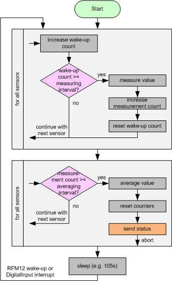
The main loop (simplified)
In general the device wakes up by the RFM12 timer to read out its sensors. The frequency of measuring can be configured very detailed by setting the following values in e2p:
- Wakeup Interval: This is the time after which the decive is woken up. The default is 105s. You could set a low value (e.g. 6s) if you want to check a sensor very often or want to calculate an average over many single measurements. On the other hand, the value shouldn't be smaller than needed, because the power consumption goes up with each measurement.
- Measuring Interval (per sensor type): This value decides after how many wake-up events a specific sensor is measured. The typical range is between 2 and 5. Most times, you want to measure all sensors every time the device wakes up. But if you have to poll one sensor very often (thus setting a small wakeup interval), you may want to measure the other values as rarely as before, which you could configure with setting the measuring interval higher.
- Averaging Interval (per sensor type): This is the (minimum) amount of measurements which are aggregated before an average is calculated. Depending on the configuration of the other sensors, it could happen that more measurements than the configured value are taken into account (see behaviour as described below).
The configuration of these values are used as follows: after waking up, the device increases a wake-up counter per sensor and reads out the sensors whose measuring interval is reached. If the amount of measurements of a sensor reaches its averaging interval, the device sends a status message. If one message is sent, the device does not send another message until it wakes up again in the next loop cycle. This is done to give receivers of the status message some time to react and send their own messages as result and to avoid collisions of multiple transmissions at the same time. As a result, it can happen that calculating an average can take more measurements into account than the selected averaging interval.
The environment sensor does not support receiving packets. Therefore it's not supported to ask the device for its current status with a "Get" message.
DigitalInput sensor
The DigitalInput "sensor" consists of up to 8 virtual port pins, which can be mapped to any of the (free) GPIO pins. For example, pin 0 could be PC2 physically and pin 1 could be PD6.
By default, the pins are read out in the configured interval like other sensors. But the DigitalInput sensor has also a special trigger / interrupt mode. When you activate it, the device wakes up immediately when the status of the pin changes and can also send the updated status immediately. You can select to send the update when the level goes up, down or when it changes.
For every pin, you can configure the ATMega's internal pull-up resistor. This resistor has typically a value of about 25 kOhms. When the interrupt mode is not used, the internal pull-up is only switched on when the digital input sensor is read out. Power consumption should be absolutely no problem in this case. But when you switch on the interrupt mode, the pull-up resisor (if configured and necessary) has to be active all the time of course. So in this case, you may want to connect an external pull-up resistor with a higher impedance instead to reduce power consumption. A value of up to 1 MOhms is usually ok.
AnalogInput sensor
The AnalogInput "sensor" consists of up to 5 virtual port pins, which can be mapped to physical pins just like the ones from the DigitalInput sensor.
The standard use-case is to measure the voltages of the pins, optionally calculate an average and send the values. Additionally, there is a configurable trigger mode. This works differently to the DigitalInput though. First off, the device can't wake up immediately after some event, but has to poll the voltages in the interval you set up. But nontheless, the trigger mode makes it possible to only react on a specific voltage level change in the sense of sending a status update.
The trigger threshold defines the level above which the voltage is considered "high". Depending on the trigger mode, you can configure the device to send an update when the level goes high, low or when it changes. To avoid sending updates too often when the voltage changes slightly around the threshold, a hysteresis value can be set. Here's an example: With a given threshold of 500mV and 100mV hysteresis, suppose that the voltage level went up from 0V to 505mV (trigger fires) and then up to a maximum voltage of 540mV. In this case, the hysteresis makes sure that the "down" trigger doesn't fire until the voltage is lower than 440mV. The behaviour in the other direction is exactly the same, only mirrored.
'What happens if the trigger does not fire at all?' you might ask. If this is the case over a long time (greater than configured measuring * averaging interval), the status is sent anyway. This behavior was chosen to make sure to inform all other devices (especially the base station) about the availability of the sensor data and that it didn't change.
Voltage converter support (for SRF02)
Typically two batteries are used to power the environment sensor. They provide a voltage of 2.2 to 3V. The SRF02 (and maybe other sensors in the future) needs a higher voltage of 5V. To make it possible to use the SRF02 with only two batteries, a voltage converter is supported to produce the needed voltage.
The voltage converter is an additional little PCB which you have to connect. If everything is done correctly, the converter is switched on directly before a distance measurement is made. Otherwise it is off and does not drain the batteries. Please read the assembly instructions for details.
Particulate Matter sensor
The sensor measures mass and number concentrations for a set of particle sizes. To minimize the message size for the measurement values but also allow other sensors to report values based on different PM sizes than the SPS30, an additional ParticulateMatterConfig message is used to tell to which sizes the measured values correspond to.
Supported Messages
- Generic_DeviceInfo_Status
- Generic_BatteryStatus_Status
- GPIO_DigitalPort_Status
- GPIO_AnalogPort_Status
- Weather_Temperature_Status
- Weather_HumidityTemperature_Status
- Weather_BarometricPressureTemperature_Status
- Environment_Brightness_Status
- Environment_Distance_Status
- Environment_ParticulateMatterConfig_Status
- Environment_ParticulateMatter_Status
E2P Device Configuration
| Offset | Block | Content | Type | Size | Description |
|---|---|---|---|---|---|
| 0 | Hardware Values for hardware setup, which have no special meaning to SHC device concepts + the DeviceType, which decides about the existence of further blocks. | DeviceType | EnumValue | 1 Bytes | The device can check with this value if the EEPROM data is meant for the actual type of device. If not, the device goes into an error mode. Values: 0 = BaseStation, 20 = EnvSensor, 40 = PowerSwitch, 45 = Controller, 50 = RGBDimmer, 60 = Dimmer, 70 = SoilMoistureMeter, 80 = Thermostat, 90 = TeaMaker |
| 8 | OsccalMode | IntValue | 1 Bytes | This value is used to change the speed of the internal oscillator. 0 = don't use OSCCAL calibration (e.g. external crystal oszillator is used). -128 = OSCCAL measure mode: the LED blinks every 60s, so the user can measure the original speed. -127..+127 = The speed is adjusted by the given amount in per mill (e.g. 10 means to speed up the device by +1%). MinVal: -128, MaxVal: 127, Default: 0 | |
| 16 | Reserved | 6 Bytes | n/a | ||
| 64 | Generic This block contains SHC configuration data which every device has. | DeviceID | UIntValue | 12 Bits | The DeviceID identifies the specific unit in the SHC network. It is used to address the device and in messages the device sends. Every device has to have a different DeviceID. MinVal: 0, MaxVal: 4095 |
| 76 | Reserved | 4 Bits | n/a | ||
| 80 | PacketCounter | UIntValue | 3 Bytes | The PacketCounter is counted up throughout the whole lifetime of the device and is used to make the encrypted packets differently from each other every time. MinVal: 0, MaxVal: 16777215 | |
| 104 | Reserved | 19 Bytes | n/a | ||
| 256 | AesKey | ByteArray | 32 Bytes | This key is used to encrypt packets before sending and also used as primary key to decrypt packets. Special devices may have additional keys in their device specific block. | |
| 512 | EnvSensor This block contains the specific configuration data that only Environment Sensor devices need. | TemperatureSensorType | EnumValue | 1 Bytes | You can choose one of the supported temperature / humidity sensors. Values: 0 = NoSensor, 1 = SHT15, 2 = DS7505, 3 = BMP085, 4 = DS18x20, 5 = SHT2x_HTU21D |
| 520 | HumiditySensorType | EnumValue | 1 Bytes | You can choose one of the supported air humidity sensors. Values: 0 = NoSensor, 1 = SHT15, 2 = SHT2x_HTU21D | |
| 528 | BarometricSensorType | EnumValue | 1 Bytes | You can choose one of the supported barometric pressure sensors. Values: 0 = NoSensor, 1 = BMP085 | |
| 536 | BrightnessSensorType | EnumValue | 1 Bytes | You can choose one of the supported light sensors. Values: 0 = NoSensor, 1 = Photocell | |
| 544 | DistanceSensorType | EnumValue | 1 Bytes | Choose one of the connected distance sensor types. Values: 0 = NoSensor, 1 = SRF02 | |
| 552 | ParticulateMatterSensorType | EnumValue | 1 Bytes | Choose one of the connected particulate matter sensor types. Values: 0 = NoSensor, 1 = SPS30 | |
| 560 | Reserved | 57 Bytes | n/a | ||
| 1016 | PowerPinMode | EnumValue | 1 Bytes | Choose the behaviour of the power pin (PD5) while measuring. It can be turned on before measuring to switch a voltage converter to produce 5V out of the 3V battery power. This is needed for some sensors which need 5V. 5VSensor_Delay1000 means that the pin is switched on when a sensor is configured which needs 5V power (currently SRF02 and SPS30). There's a delay of 1000ms after switching the pin to stabilize the voltage and to ensure the sensor works correctly. Off means the power pin is always off. Values: 0 = Off, 1 = 5VSensor_Delay1000 | |
| 1024 | WakeupInterval | EnumValue | 2 Bytes | Decide after which time the device should be woken up by the RFM12B transceiver to measure or send values. Values: 1018 = 2s, 1274 = 4s, 1467 = 6s, 1530 = 8s, 1692 = 10s, 1770 = 15s, 1948 = 20s, 2027 = 30s, 2224 = 45s, 2421 = 60s, 2450 = 75s, 2480 = 90s, 2509 = 105s, 2538 = 2m, 2736 = 3m, 2794 = 4m, 2962 = 5m, 3050 = 8m, 3248 = 12m, 3292 = 15m, 3474 = 20m, Default: 2509 | |
| 1040 | TemperatureMeasuringInterval | UIntValue | 1 Bytes | The number of times the device wakes up before this value is measured. MinVal: 1, MaxVal: 255, Default: 1 | |
| 1048 | TemperatureAveragingInterval | UIntValue | 1 Bytes | The number of values whose average is calculated before sending. MinVal: 1, MaxVal: 16, Default: 4 | |
| 1056 | HumidityMeasuringInterval | UIntValue | 1 Bytes | The number of times the device wakes up before this value is measured. MinVal: 1, MaxVal: 255, Default: 1 | |
| 1064 | HumidityAveragingInterval | UIntValue | 1 Bytes | The number of values whose average is calculated before sending. MinVal: 1, MaxVal: 16, Default: 4 | |
| 1072 | BarometricMeasuringInterval | UIntValue | 1 Bytes | The number of times the device wakes up before this value is measured. MinVal: 1, MaxVal: 255, Default: 1 | |
| 1080 | BarometricAveragingInterval | UIntValue | 1 Bytes | The number of values whose average is calculated before sending. MinVal: 1, MaxVal: 16, Default: 4 | |
| 1088 | BrightnessMeasuringInterval | UIntValue | 1 Bytes | The number of times the device wakes up before this value is measured. MinVal: 1, MaxVal: 255, Default: 1 | |
| 1096 | BrightnessAveragingInterval | UIntValue | 1 Bytes | The number of values whose average is calculated before sending. MinVal: 1, MaxVal: 16, Default: 4 | |
| 1104 | DistanceMeasuringInterval | UIntValue | 1 Bytes | The number of times the device wakes up before this value is measured. MinVal: 1, MaxVal: 255, Default: 4 | |
| 1112 | DistanceAveragingInterval | UIntValue | 1 Bytes | The number of values whose average is calculated before sending. MinVal: 1, MaxVal: 16, Default: 1 | |
| 1120 | DigitalInputMeasuringInterval | UIntValue | 1 Bytes | The number of times the device wakes up before this value is measured. MinVal: 1, MaxVal: 255, Default: 1 | |
| 1128 | DigitalInputAveragingInterval | UIntValue | 1 Bytes | The number of values whose average is calculated before sending. MinVal: 1, MaxVal: 16, Default: 6 | |
| 1136 | AnalogInputMeasuringInterval | UIntValue | 1 Bytes | The number of times the device wakes up before this value is measured. MinVal: 1, MaxVal: 255, Default: 1 | |
| 1144 | AnalogInputAveragingInterval | UIntValue | 1 Bytes | The number of values whose average is calculated before sending. MinVal: 1, MaxVal: 16, Default: 6 | |
| 1152 | ParticulateMatterMeasuringInterval | UIntValue | 1 Bytes | The number of times the device wakes up before this value is measured. MinVal: 1, MaxVal: 255, Default: 1 | |
| 1160 | ParticulateMatterAveragingInterval | UIntValue | 1 Bytes | The number of values whose average is calculated before sending. MinVal: 1, MaxVal: 16, Default: 4 | |
| 1168 | Reserved | 46 Bytes | n/a | ||
| 1536 | DigitalInputPin | EnumValue[8] | 1 Bytes x 8 | You can choose up to 8 GPIO pins as digital input. The enum values are counting through every pin from port B, C and D, leaving out the pins that are not accessible because otherwise used. Values: 0 = Unused, 2 = PB1, 3 = PB2, 7 = PB6, 8 = PB7, 10 = PC1, 11 = PC2, 12 = PC3, 13 = PC4, 14 = PC5, 20 = PD3, 21 = PD4, 22 = PD5, 23 = PD6 | |
| 1600 | DigitalInputPullUpResistor | BoolValue[8] | 1 Bytes x 8 | Decide if you want to switch on the pull-up resistor at each input pin you have chosen. (If you connect a simple switch connected to ground, you typically want this.) | |
| 1664 | DigitalInputTriggerMode | EnumValue[8] | 1 Bytes x 8 | The mode decides how the device detects changes and when a new message is sent. Off means the value is sent after a full cycle time only. In any other case, the device wakes up immediately after a change. A status is then sent either when the level is going up, down or on change. Values: 0 = Off, 1 = Up, 2 = Down, 3 = Change | |
| 1728 | Reserved | 40 Bytes | n/a | ||
| 2048 | AnalogInputPin | EnumValue[5] | 1 Bytes x 5 | You can choose up to 5 ADC pins as analog input. The enum values are a reduced set of the ones from the digital input. Values: 0 = Unused, 10 = PC1, 11 = PC2, 12 = PC3, 13 = PC4, 14 = PC5 | |
| 2088 | AnalogInputTriggerMode | EnumValue[5] | 1 Bytes x 5 | The mode decides how the device detects changes and when a new message is sent. The voltage level is measured in the configured interval. When the mode is set to off, the status is only sent after a full averaging cycle. In the other modes, a status is sent when the level is going up, down or changes according to the trigger level. Values: 0 = Off, 1 = Up, 2 = Down, 3 = Change | |
| 2128 | AnalogInputTriggerThreshold | UIntValue[5] | 2 Bytes x 5 | The threshold in millivolts is used when the trigger mode is on. MinVal: 0, MaxVal: 1100 | |
| 2208 | AnalogInputTriggerHysteresis | UIntValue[5] | 2 Bytes x 5 | The hysteresis in millivolts is used when the trigger mode is on. It can avoid the trigger firing too often if you measure a slighty changing voltage. Because of noise and accuracy limits of the ADC, you should set a positive hysteresis in any case. MinVal: 0, MaxVal: 1100 | |
| 2288 | Reserved | 34 Bytes | n/a | ||
| 2560 | Reserved | 704 Bytes | n/a |
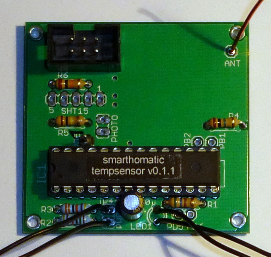
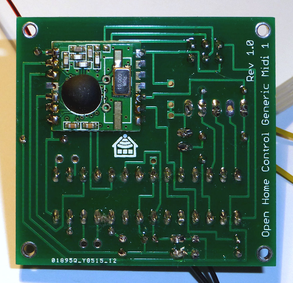
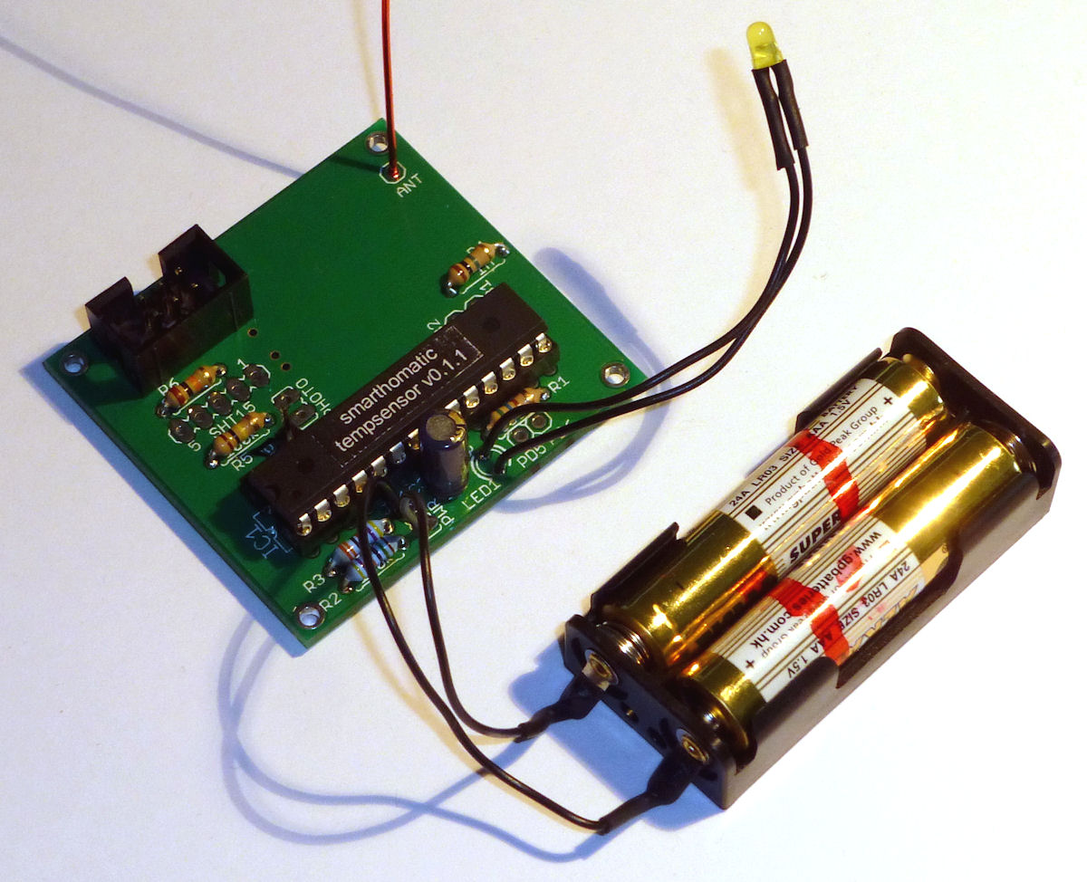
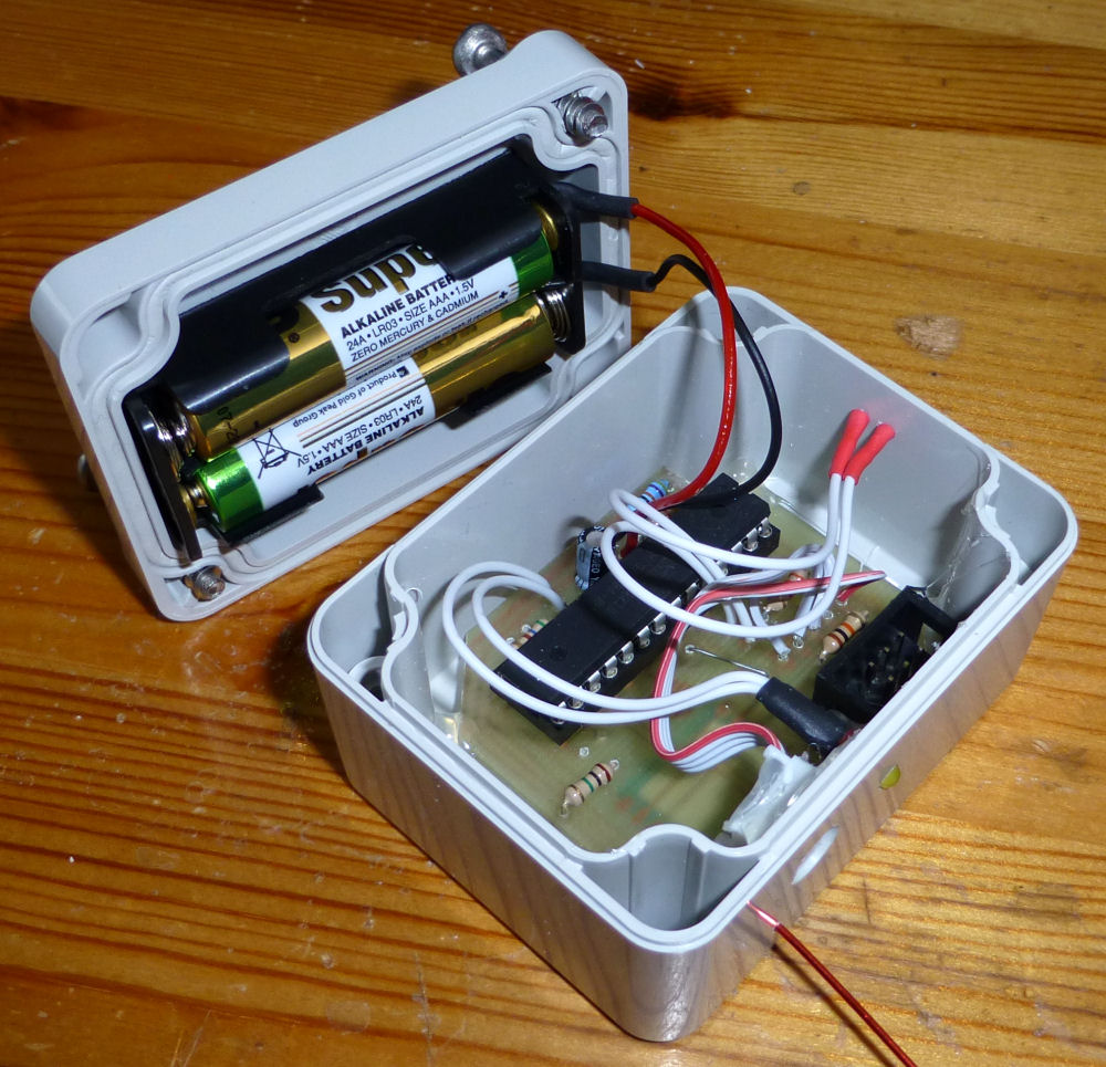
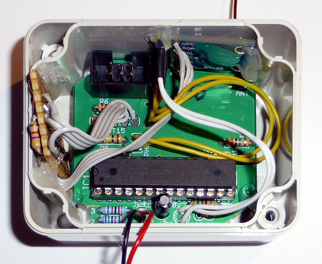
Hardware Overview (THT)
| PCB | Generic Midi PCB Conventional THTThrough hole technology This is the conventional technique to stick pins of components through the PCB and solder them. This is easy to build up, unlinke using SMD components. (non-SMD) 45 x 48 mm |
|---|---|
| Microcontroller | ATMega 328P-PU (28-pin PDIP) |
| Clock Source | 1 MHz internal R/C oscillator |
| RFM Transceiver Mode | TX only |
| UART | only debug TX |
| Power | 2x AA battery (3V) |
Schematics

Layout

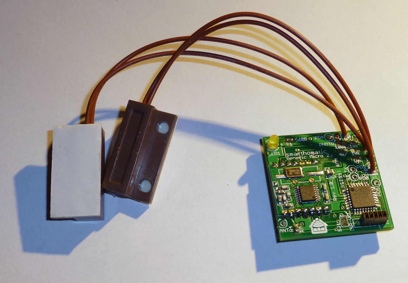
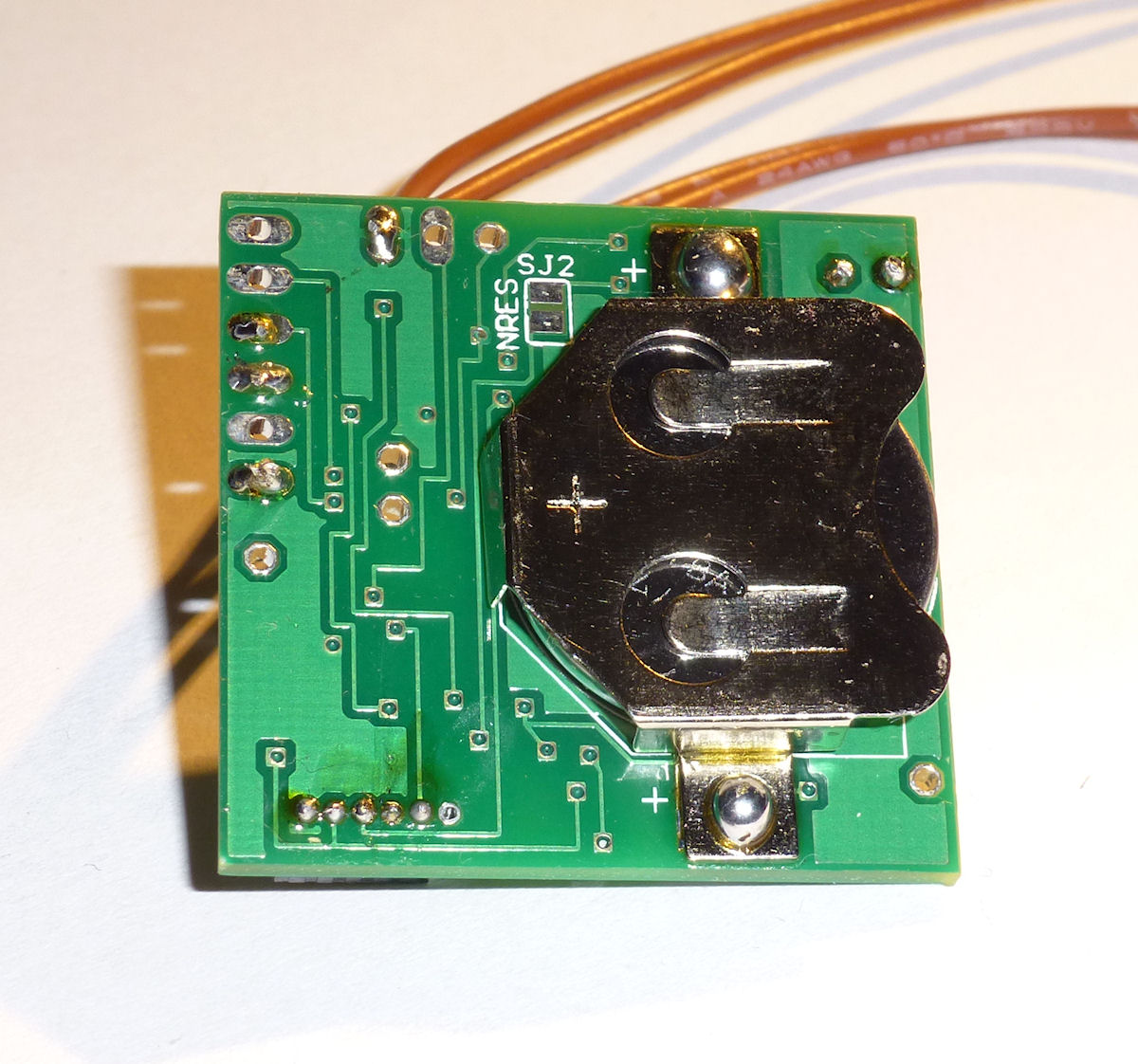
Hardware Overview (SMD)
| PCB | Generic Micro 2 PCB SMDSurface-mounted device Using this technique, the components are soldered directly to the surface of the PCB. The components are often very small. Their pin pitch is also small. Building up these devices needs some experience in soldering. 33 x 33 mm |
|---|---|
| Microcontroller | ATMega 328P-AU (32-pin TQFP) |
| Clock Source | 1 MHz internal R/C oscillator |
| RFM Transceiver Mode | TX only |
| UART | only debug TX |
| Power | 1x CR 2032 battery (3V) |
Schematics

Layout

Download
- Firmware Builds for the ATMega
- Hardware Schematics + Layout at GitHub
- SourceCode at GitHub
Assembly Instructions
Look into the Wiki for assembly instructions for this device. It would be appreciated if you correct or enhance the description whenever you find potential for improvement.